
Blade machining process

A processing technology and blade technology, which is applied in the field of aero-engine machinery, can solve problems such as high requirements, difficult processing, and complex shapes, and achieve the effects of reducing equipment costs, reliable and stable processing, and reducing repeatability errors

Active Publication Date: 2019-12-03
AECC AVIATION POWER CO LTD
View PDF8 Cites 5 Cited by
  • Summary
  • Abstract
  • Description
  • Claims
  • Application Information

AI Technical Summary

Problems solved by technology

It has complex shape, high requirements and difficult processing

Method used


Image

  • Blade machining process
  • Blade machining process
  • Blade machining process

Examples


Embodiment Construction

[0058] The present invention will be described in detail below in conjunction with the accompanying drawings and specific embodiments.

[0059] In describing the present invention, it should be understood that the terms "center", "longitudinal", "transverse", "upper", "lower", "front", "rear", "left", "right", " The orientations or positional relationships indicated by "vertical", "horizontal", "top", "bottom", "inner" and "outer" are based on the orientations or positional relationships shown in the drawings, and are only for the convenience of describing the present invention and Simplified descriptions, rather than indicating or implying that the device or element referred to must have a particular orientation, be constructed and operate in a particular orientation, and thus should not be construed as limiting the invention. In addition, the terms "first" and "second" are used for descriptive purposes only, and cannot be interpreted as indicating or implying relative import...


PUM


Abstract

The invention discloses a blade machining process. The process dispersion principle is fully adopted; by utilizing a common plane abrasion device, the cost of the device is reduced and, flow line production can be carried out on a production site in batches; meanwhile, a low-melting-point alloy precise positioning mode is adopted, the machining benchmark is converted, a space positioning point isconverted into a plane, so that the machining process is reliable and stable, the production efficiency is improved, the machining quality is guaranteed, large-batch turbine guide blade production canbe met, and the process can be widely applied to machining of aero-engines and turbine guide blades of gas turbines.

Description

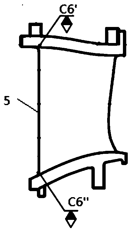
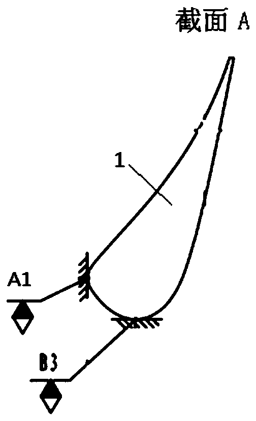
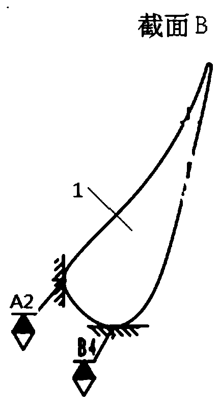
technical field [0001] The invention belongs to the technical field of aero-engine machinery, and in particular relates to a blade processing technology. Background technique [0002] The turbine guide vane is located in the part of the aero-engine with the highest temperature, the most complex stress and the harshest environment, and is known as the "jewel in the crown". The exterior structure is composed of the blade body and the edge plate, and the inner cavity is hollow, and the surface of the blade body is covered with air film holes. It is complex in shape, demanding and difficult to process. The main materials are DZ40M, IC10, DD5, DD6, etc. At present, the turbine guide vanes are generally welded by single-joint blades to form double-joint blades. The single blade is precisely cast without margin, and the inner and outer edge plate wedge surfaces and end faces are machined. Establish a machining benchmark for the subsequent precision machining of double-connected ...

Claims


Application Information

Patent Timeline
Patent Type & Authority Applications(China)
IPC IPC(8): B23P15/02B24B1/00
CPCB23P15/02B24B1/00
Inventor 张澜禹李绍鹏李晨刘海滨王冬冯永龙齐永超陈伟
Owner AECC AVIATION POWER CO LTD
Learn More