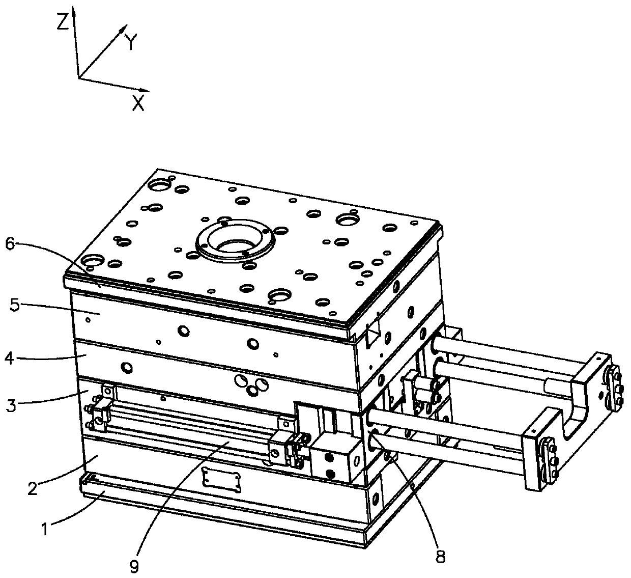
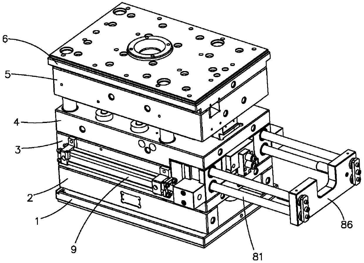
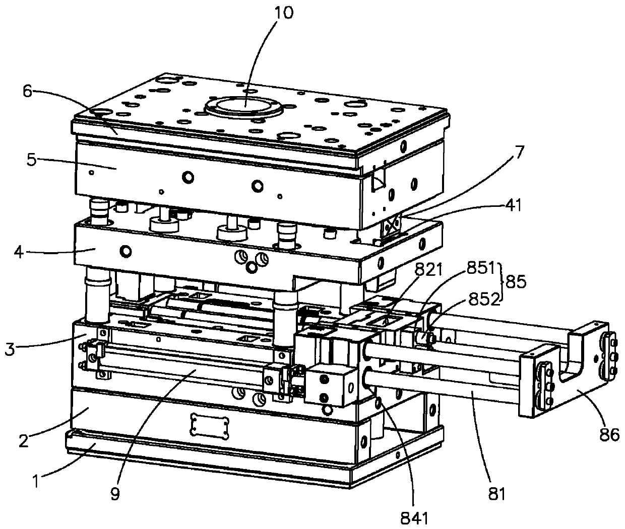
Demolding structure of long sliding block core-pulling mold and demolding method thereof

A slider core-pulling and slider module technology, which is applied in the field of injection molding, can solve problems such as impact damage, deformation of tubular plastic parts, and excessive shape of injection molds, and achieve stable performance, simple structure, and improved product yield.

Pending Publication Date: 2019-12-03
KUNSHAN JIAHUA AUTOMOTIVE ELECTRONICS TECH CO LTD
View PDF0 Cites 2 Cited by
  • Summary
  • Abstract
  • Description
  • Claims
  • Application Information

AI Technical Summary

Problems solved by technology

So easy to deform or impact damage to tubular plastic parts
In addition, the formatio

Method used


Image

  • Demolding structure of long sliding block core-pulling mold and demolding method thereof
  • Demolding structure of long sliding block core-pulling mold and demolding method thereof
  • Demolding structure of long sliding block core-pulling mold and demolding method thereof

Examples


Embodiment Construction

[0025] It should be noted that, in the case of no conflict, the embodiments of the present invention and the features in the embodiments can be combined with each other. The present invention will be described in detail below with reference to the accompanying drawings and examples.

[0026] In the description of the present invention, it should be noted that unless otherwise specified and limited, the terms "installation", "connection" and "connection" should be understood in a broad sense, for example, it can be a fixed connection or a detachable connection. Connected, or integrally connected; it can be mechanically connected or electrically connected; it can be directly connected or indirectly connected through an intermediary, and it can be the internal communication of two components. Those of ordinary skill in the art can understand the specific meanings of the above terms in the present invention in specific situations.

[0027] In the description of the present invent...


PUM


Abstract

The invention discloses a demolding structure of a long sliding block core-pulling mold. The demolding structure comprises a lower die plate, an upper die plate located above the lower die plate, a material stirring plate located above the upper die plate, a shoveling machine, a sliding block module and an oil cylinder assembly. A die cavity is formed between the upper die plate and the lower dieplate; the material stirring plate, the upper template and the lower template can realize mold opening or mold closing along the up-and-down direction; the sliding block module is fixed to the right side of the demolding structure of the long sliding block core-pulling mold. The sliding block module comprises a sliding block and an insert, one end of the insert is fixed to the sliding block, the other end of the insert protrudes into the die cavity, the oil cylinder assembly drives the sliding block and the lower die plate to move relatively, the right end of the upper die plate penetrates inthe vertical direction to form a shoveling machine hole, one end of the shoveling machine is fixed to the material stirring plate, and the other end of the shoveling machine penetrates through the shoveling machine hole to be linked with the sliding block. The shoveling machine is designed to be matched with the sliding block, so that the initial adhesive force between the insert and the injectionmolding part is removed during mold opening, the insert cannot be taken out of the injection molding part when the air cylinder assembly drives the insert to be pulled out, and the product yield is further improved.

Description


Claims


Application Information

Patent Timeline
Owner KUNSHAN JIAHUA AUTOMOTIVE ELECTRONICS TECH CO LTD
Why Eureka
Try Eureka