
Expectant-direct-driven leg-foot super-dynamic robot based on multi-joint coupling

A robot, leg-foot technology, applied in the field of robots, can solve the problems of damaging the motor drive system, limiting the application range of hydraulic drive robots, reducing the joint response speed and joint movement speed of the control system, etc., so as to improve the ultra-dynamic movement ability and energy Use efficiency and reduce the effect of balanced load

Active Publication Date: 2019-12-03
BEIJING INSTITUTE OF TECHNOLOGYGY
View PDF5 Cites 7 Cited by
  • Summary
  • Abstract
  • Description
  • Claims
  • Application Information

AI Technical Summary

Problems solved by technology

[0004] Although the hydraulic drive improves the power density of the robot drive, the noise of the hydraulic pump and the oil leakage of the hydraulic cylinder greatly limit the application range of the hydraulic drive robot.
[0005] Although the motor drive system with a high reduction ratio increases the drive density, it greatly reduces the response speed and joint movement speed of the control system joints, and at the same time increases the inertia, friction and other parameters of the system, reducing the ultra-dynamic motion capability of the robot.
[0006] Existing direct-drive robots also face a serious problem, that is, the drive system heats up when it is stationary for a long time, resulting in a waste of energy
For example, a serious engineering problem faced by motor-driven direct-drive and collimated-drive robots is the heating of the motor, especially when the robot needs to move for a long time or maintain static stability, it will generate a lot of heat, reduce energy utilization, and may Damage to the motor drive system

Method used


Image

  • Expectant-direct-driven leg-foot super-dynamic robot based on multi-joint coupling
  • Expectant-direct-driven leg-foot super-dynamic robot based on multi-joint coupling
  • Expectant-direct-driven leg-foot super-dynamic robot based on multi-joint coupling

Examples


Embodiment Construction

[0031] In order to enable those skilled in the art to better understand the solution of the present application, the technical solution in the embodiment of the application will be clearly and completely described below in conjunction with the accompanying drawings in the embodiment of the application. Obviously, the described embodiment is only It is an embodiment of a part of the application, but not all of the embodiments. Based on the embodiments in this application, all other embodiments obtained by persons of ordinary skill in the art without creative efforts shall fall within the scope of protection of this application.

[0032] It should be noted that the terms "first" and "second" in the description and claims of the present application and the above drawings are used to distinguish similar objects, but not necessarily used to describe a specific sequence or sequence. It should be understood that the data so used may be interchanged under appropriate circumstances for...


PUM


Abstract

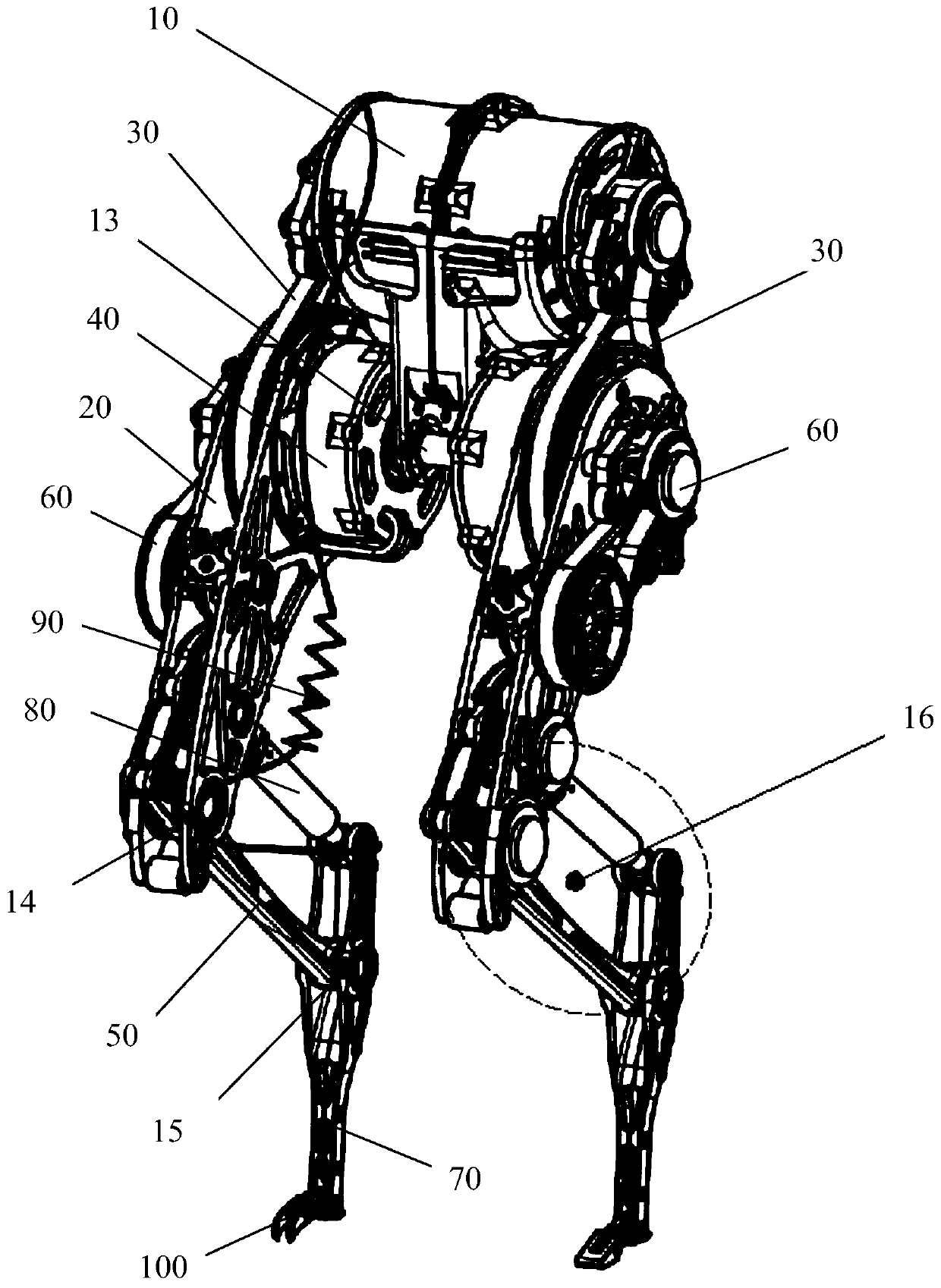
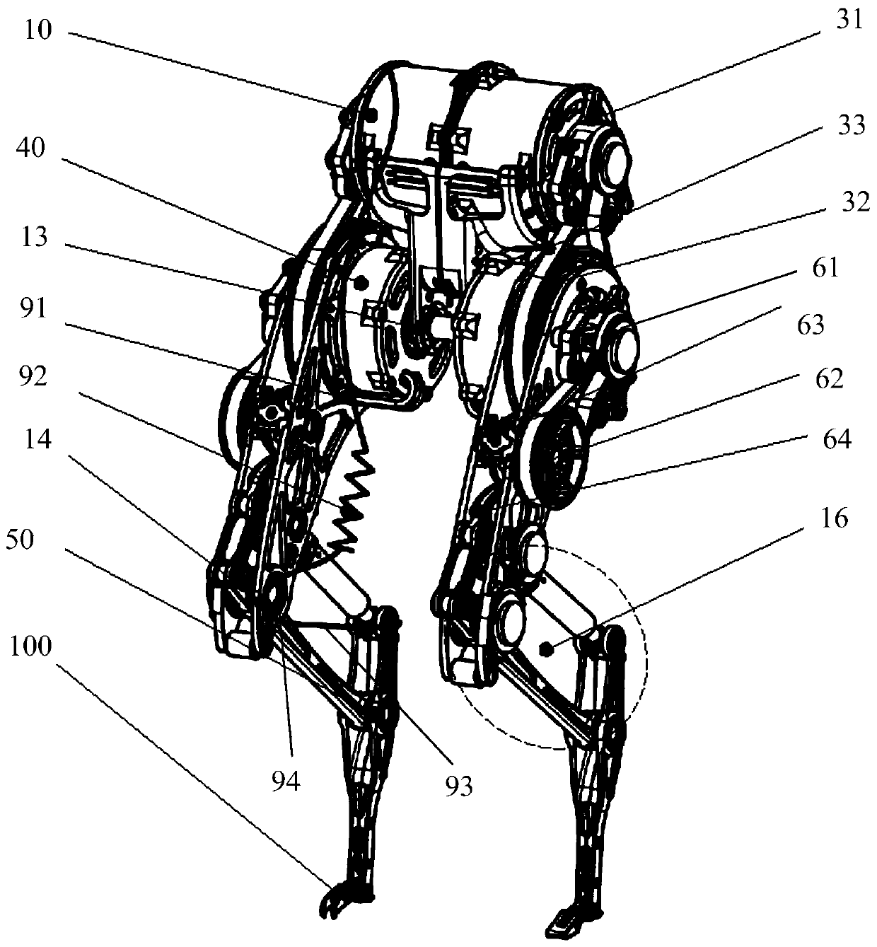
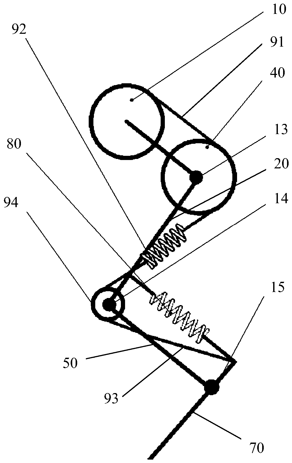
The embodiment of the invention discloses an expectant-direct-driven leg-foot super-dynamic robot based on multi-joint coupling. A robot supporting leg can comprise a hip joint driving device, a thighmechanism, a knee joint driving device, a shank mechanism, a leg-foot mechanism and a joint coupling assembly. According to the robot supporting leg, on the one hand, the action principle of a bionictransarticular tendon-ligament in biodynamic motion is introduced, function extension is performed, the synergistic effect of joints can be driven, the jumping ability of the robot is improved, meanwhile the balance point which is static and free of motor power input is formed, and the problem of motor heating during long-time stationary state of a direct-driven robot can be solved; and on the other hand, by combining with a second speed-reducing transmission mechanism, a robot which adopts the robot supporting leg can be formed into the expectant-direct-driven leg-foot robot, and the robot super-dynamic movement ability is improved.

Description

technical field [0001] The present application relates to the technical field related to robots, in particular to a multi-joint coupling-based collimation-driven leg-foot hyperdynamic robot. Background technique [0002] The key technology of ultra-dynamic (such as jumping) moving robots is that the drive system can provide a high power density output, and at the same time have high requirements for the response bandwidth of the control system. [0003] At present, in order to increase the output power of robot joints, hydraulic drive and motor drive with large reduction ratio are mostly used. These components increase the output power while increasing the inertia and friction of the robot system. At the same time, the large reduction ratio reduces the response speed of the control system. [0004] Although the hydraulic drive improves the power density of the robot drive, the noise of the hydraulic pump and the oil leakage of the hydraulic cylinder greatly limit the applica...

Claims


Application Information

Patent Timeline
Patent Type & Authority Applications(China)
IPC IPC(8): B62D57/032
CPCB62D57/032
Inventor 黄强孟非王磊刘华欣范徐笑
Owner BEIJING INSTITUTE OF TECHNOLOGYGY
Learn More