Rotary wheel and turbine dual-power steam turbine

A steam turbine and dual-power technology, applied to engine components, machines/engines, mechanical equipment, etc., can solve the problems of high heat energy consumption, small mechanical energy, and more mechanical energy, and achieve high power, large mechanical energy, and low energy consumption.

Inactive Publication Date: 2019-12-03
高扬
View PDF0 Cites 0 Cited by
  • Summary
  • Abstract
  • Description
  • Claims
  • Application Information

AI Technical Summary

Problems solved by technology

[0003] Every feature of the windmill principle will cause great functional loss to the steam turbine, and there are many technical defects: 1) The first feature of the windmill principle: a large number of blades are arranged on the impeller shaft, and the blades rotate in the cylinder The space passed by one week forms the cylinder volume of the steam turbine. The internal space of the cylinder is large, and the heat energy consumed to maintain the work is large; the centripetal vertical height of the blade blade is large, and the fan peak and fan root of the blade blade are within the unit area. The heat energy consumed is the same, but the mechanical energy produced by them is different. The long arm of the fan peak, that is, the large torque, generates more mechanical energy, while the short arm of the fan root means that the torque is small, and the mechanical energy generated is also small.
[0005] Therefore, the steam turbine based on the windmill principle has high thermal energy consumption, low mechanical efficiency, and small power per unit, which can no longer meet the requirements of modern low-carbon life concepts.

Method used


Image

  • Rotary wheel and turbine dual-power steam turbine
  • Rotary wheel and turbine dual-power steam turbine
  • Rotary wheel and turbine dual-power steam turbine

Examples


Embodiment Construction

[0025] The present invention will be further described below in conjunction with accompanying drawing.

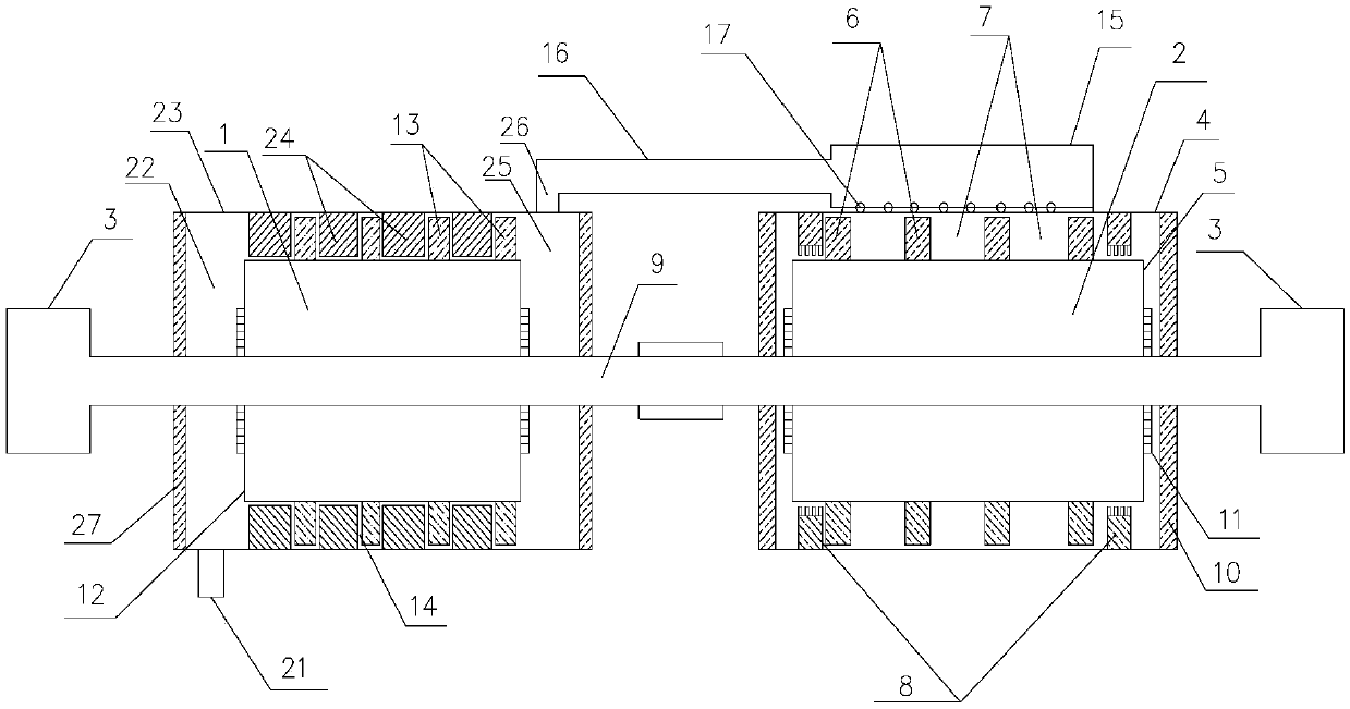
[0026] figure 1 Shown is a structural diagram of an embodiment of the present invention. A rotary wheel and turbine dual-power steam turbine, comprising a rotary turbine 1 and a turbine 2 rotating around the same rotating shaft (9), the rotary turbine 1 and the turbine 2 are connected through a gas delivery pipe 16, and are respectively arranged at the left and right ends of the rotary shaft 9 There is a generator 3 that is connected to the rotary machine 1 and the turbine 2, so that the mechanical energy generated by each can be matched and supplemented to each other, so as to achieve the sharing of mechanical energy.

[0027] The rotary machine 1 includes a rotary wheel cylinder 23 and a cylindrical hollow rotary wheel 12. The rotary wheel cylinder 23 buckles the rotary wheel 12 in it. The middle of the cylindrical rotary wheel cylinder 23 is a working chamber, and the t...


PUM


Abstract

The invention provides a rotary wheel and turbine dual-power steam turbine. The rotary wheel and turbine dual-power steam turbine comprises a rotary wheel machine (1), a turbine machine (2) and powergeneration devices (3) on the two sides of the turbine machine (2); the rotary wheel machine (1) comprises a hollow rotary wheel (12) and a rotary wheel cylinder body (23); rotary plates (13) are arranged on the hollow rotary wheel (12), turning grids (24) are arranged on the inner wall of the rotary wheel cylinder body (23), and air channels (24-1) in the turning grids correspond to the rotary plates on the hollow rotary wheel one to one in position and are perpendicular to the rotary plates on the hollow rotary wheel; the turbine machine(2) comprises a turbine cylinder body (4), a hollow turbine (5), an air inlet containing cavity (15), an air outlet containing cavity (18), an air inlet arc-shaped cylinder, an air outlet arc-shaped cylinder, a backflow restraining arc-shaped cylinder andan arc-shaped working cylinder. In the arc-shaped working cylinder, the impact direction of steam is always perpendicular to the vortex plate and consistent with the rotating direction of the vortexplate. The problem that a traditional steam turbine is low in mechanical efficiency due to the windmill principle is solved, and the mechanical efficiency of the steam turbine is remarkably improved by creatively utilizing the typhoon principle.

Description

technical field [0001] The invention relates to the field of steam turbines, in particular to a combined device of a rotary turbine and a turbine. Background technique [0002] Existing steam turbines use the windmill principle. The windmill principle type steam turbine has the following characteristics: 1. The first feature of the windmill principle type steam turbine: blades are arranged on the impeller shaft. 2. The second characteristic of the windmill principle steam turbine: the movement direction of the high-pressure steam in the cylinder is parallel to the axis of the impeller, and the angle between the movement track of the high-pressure steam and the axis is 0°. 3. The third feature of the windmill principle steam wheel: the direction of movement of the high-pressure steam in the cylinder is perpendicular to the direction of rotation of the impeller. 4. The fourth feature of the windmill principle steam turbine: the movement direction of the high-pressure steam c...

Claims


Application Information

Patent Timeline
IPC IPC(8): F01D15/10F01D5/02
CPCF01D5/02F01D15/10
Inventor 高宏亮高扬
Owner 高扬
Why Eureka
Try Eureka