
Wheel reductor structure

A wheel-side reducer and hub technology, applied in gear transmission, gear lubrication/cooling, belt/chain/gear, etc., can solve the problem that the wheel-side reducer cannot meet the market demand, so as to meet the market demand and reduce the weight. , The effect of improving transmission efficiency

Active Publication Date: 2019-12-03
FAW JIEFANG AUTOMOTIVE CO
View PDF9 Cites 2 Cited by
  • Summary
  • Abstract
  • Description
  • Claims
  • Application Information

AI Technical Summary

Problems solved by technology

[0007] The purpose of the present invention is to provide a wheel-side reducer structure to solve the problem that the wheel-side reducer with a large speed ratio cannot meet the market demand

Method used


Image

  • Wheel reductor structure
  • Wheel reductor structure
  • Wheel reductor structure

Examples


Embodiment Construction

[0033] The present invention will be further described in detail below in conjunction with the accompanying drawings and embodiments. It should be understood that the specific embodiments described here are only used to explain the present invention, but not to limit the present invention. In addition, it should be noted that, for the convenience of description, only some structures related to the present invention are shown in the drawings but not all structures.

[0034] In the description of the present invention, unless otherwise clearly specified and limited, the terms "connected", "connected" and "fixed" should be understood in a broad sense, for example, it can be a fixed connection, a detachable connection, or an integrated ; It can be a mechanical connection or an electrical connection; it can be a direct connection or an indirect connection through an intermediary, and it can be the internal communication of two components or the interaction relationship between two ...


PUM


Abstract

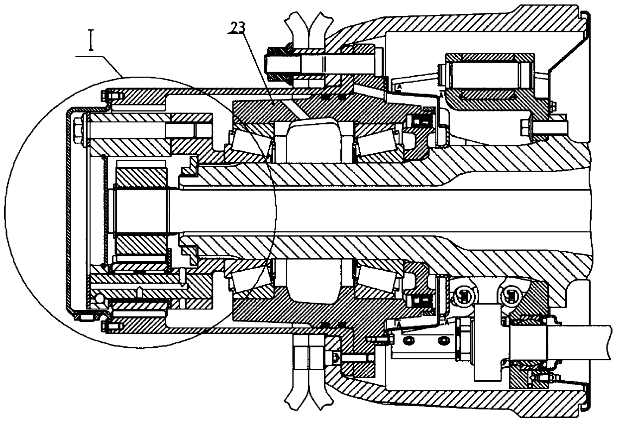
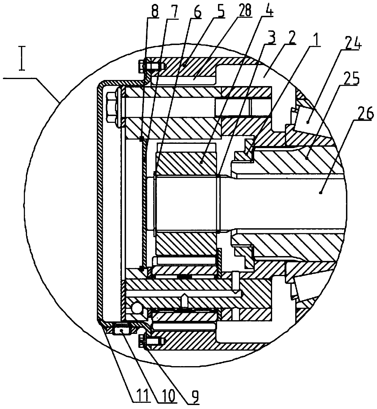
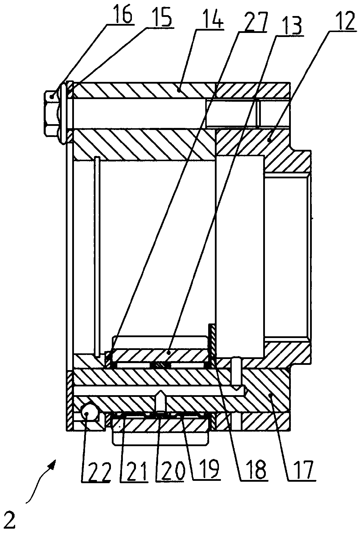
The invention belongs to the technical field of automobiles. The invention discloses a wheel reductor structure. The structure comprises a sun gear, a plurality of planet gears, a half shaft, an end cover, a wheel reductor shell, a hub, a planet carrier and a gear ring, and also comprises a shaft sleeve and a bracket fixed to the planet carrier, wherein the half shaft penetrates through the shaftsleeve from the middle part and can freely rotate in the shaft sleeve; the bracket is fixed on the shaft sleeve; the sun gear is fixed on the half shaft to be used as power input; and the gear ring isfixed on the wheel reductor shell to be used as power output. The wheel reductor structure has the beneficial effects that the planet carrier is fixed, the sun gear is adopted as power input, and thegear ring is adopted as power output, so that the reduction ratio is reduced, the transmission efficiency is improved, and market requirements are better met; meanwhile, the gear ring is integrated on the wheel reductor shell so that the weight of the wheel reductor is reduced than that in an existing structure that the gear ring and the wheel reductor shell are arranged separately.

Description

technical field [0001] The invention relates to the technical field of automobiles, in particular to a wheel-side reducer structure. Background technique [0002] The wheel reducer is one of the components of the automobile axle, which can reduce the speed transmitted from the main reducer and increase the torque of the gear end. In the domestic wheel reducer, the sun gear is generally used as the power input, and the planetary gear is used as the power output. The common structures are as follows: [0003] Patent Document 1 (CN202992122U) discloses a heavy-duty vehicle axle wheel reducer structure, including sun gear, sun wheel outer washer, half shaft, end cover, wheel reducer housing, multiple planetary wheels, collar and A plurality of planetary wheel washers, the inner diameter of the outer washer of the sun wheel is larger than the outer diameter of the sun wheel, a retaining ring is arranged between the sun wheel and the collar, and an axial limit device of the half ...

Claims


Application Information

Patent Timeline
Patent Type & Authority Applications(China)
IPC IPC(8): F16H1/32F16H57/08F16H57/04
CPCF16H1/32F16H57/0424F16H57/0482F16H57/082F16H2001/327
Inventor 冯涛王震苗士军
Owner FAW JIEFANG AUTOMOTIVE CO
Learn More