Tank truck sampling device

A sampling device and tanker technology, which is applied to sampling devices, sampling, measuring devices, etc., can solve the problems of inconvenient sampling work, affecting monitoring accuracy, and gushing out, and achieve the effect of saving manpower

Pending Publication Date: 2019-12-03
江苏海丰交通设备科技有限公司
View PDF1 Cites 3 Cited by
  • Summary
  • Abstract
  • Description
  • Claims
  • Application Information

AI Technical Summary

Problems solved by technology

[0002] In order to solve the sampling problem of traditional liquid tank trucks—①When sampling, the liquid to be tested will react with the air, which affects the monitoring accuracy; ②The risk of falling when the sampling personnel use the sampling device installed on the roof; The sampling device at the bottom of the liquid tank car will cause sampling difficulties due to excessive water pressure. The patent with the authorized announcement number CN207832522U proposes "a tank car full liquid column sampling device", including the tank car body, sampling branch pipe, sampling main pipe, recovery pump and recovery Although the above-mentioned structure can solve the problems such as the contact between the liquid to be tested and the air, and the difficulty for the staff to get on and off the roof, it still has the following defects: ①The sampling tube is set near the bottom of the compartment, and the sampling personnel need to bend down or Liquid sampling can only be carried out by squatting down, which brings great inconvenience to the sampling work; ②The sampling main pipe is vertically arranged, if there is more liquid to be tested in the sampling main pipe, a relatively large pressure will still be generated, and the liquid will will gush out, which is not conducive to sampling

Method used


Image

  • Tank truck sampling device
  • Tank truck sampling device
  • Tank truck sampling device

Examples


Embodiment Construction

[0012] The technical solutions in the embodiments of the present invention will be clearly and completely described below with reference to the accompanying drawings in the embodiments of the present invention. Obviously, the described embodiments are only a part of the embodiments of the present invention, but not all of the embodiments. Based on the embodiments of the present invention, all other embodiments obtained by those of ordinary skill in the art without creative efforts shall fall within the protection scope of the present invention.

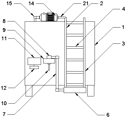
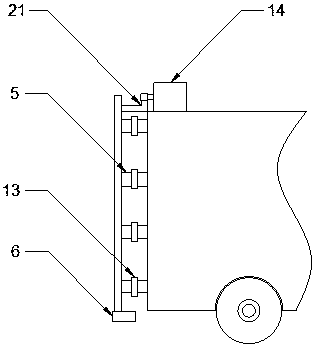
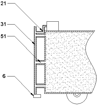
[0013] see Figure 1-Figure 3 , In the embodiment of the present invention, a tank truck sampling device includes: a vehicle body 1, a connecting ladder and a transfer box 6, the connecting ladder includes a left pillar 2 and a right pillar 3, wherein the left pillar 2 and the right pillar 3 are arranged in parallel and A plurality of pedals 4 are welded between the left strut 2 and the right strut 3 . The left pillar 2, the right pi...


PUM


Abstract

The invention discloses a tank truck sampling device comprising a truck body, a connecting ladder and a transfer box The connecting ladder consists of a left supporting column and a right supporting column; a pedal is welded between the left supporting column and the right supporting column; a connecting rod is welded between the pedal and the truck body; and a liquid outlet pipe is arranged in the connecting rod. A first return pipe is arranged in the left supporting column; and one end of the first return pipe penetrates the bottom of the left supporting column and is connected with the transfer box. According to the invention, liquid in the truck body is led to the transfer box through the liquid outlet pipe and a backflow pipe, the liquid in the transfer box is pumped into the samplingbox through the micro pump, and then a liquid sample is taken out through a sampling interface. During the process, the operator can control on / off of an electric control valve and starting-shutdownof a micro pump through a touch screen, so that the manpower is saved. After sampling ending, the operator can pump liquid in the sampling box back into the truck body through the water pump and the whole pipeline system is totally closed, so that a phenomenon that the detection precision is affected by the contact of to-be-detected liquid with air is avoided effectively.

Description

technical field [0001] The invention relates to the field of liquid sampling equipment, in particular to a tank truck sampling device. Background technique [0002] In order to solve the sampling problems of traditional liquid tankers: ① the liquid to be tested will react with the air during sampling, which affects the monitoring accuracy; ② the risk of falling when the sampling personnel use the sampling device installed on the roof of the vehicle; ③ set in the The sampling device at the bottom of the liquid tanker will be difficult to sample due to excessive water pressure. The patent with the authorization announcement number CN207832522U proposes "a full liquid column sampling device for a tanker", including the tanker body, sampling branch pipe, sampling manifold, recovery pump and recovery Although the above structure can solve the problems of contact between the liquid to be tested and the air and the difficulty of getting on and off the roof of the vehicle, it still ...

Claims


Application Information

Patent Timeline
Patent Type & Authority Applications(China)
IPC IPC(8): G01N1/14
CPCG01N1/14G01N2001/1418
Inventor 温永嘉邓淑雅刘伟
Owner 江苏海丰交通设备科技有限公司
Why Eureka
Try Eureka