A long-distance overhead high-tensile performance cable
A high-strength, long-distance technology, applied in the direction of insulated cables, cables, circuits, etc., can solve problems such as cable breakage, extended distance, and inseparable from iron towers, so as to achieve good structural stability, reduce curvature and bending, and increase The effect of tensile properties
- Summary
- Abstract
- Description
- Claims
- Application Information
AI Technical Summary
Problems solved by technology
Method used
Image
Examples
Embodiment 1
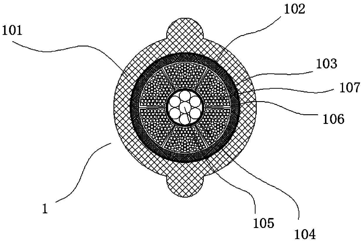
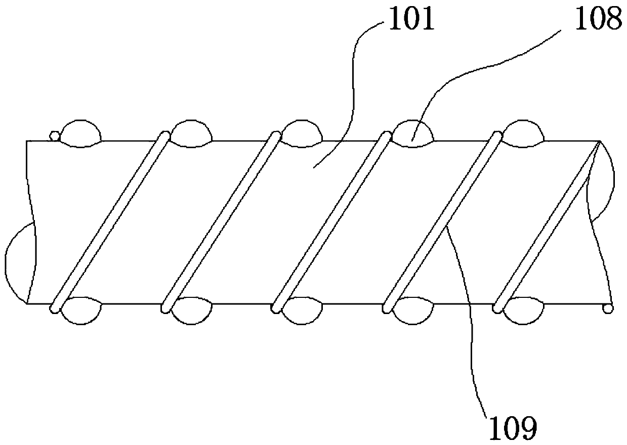
[0024] refer to figure 1 and figure 2 A long-distance overhead high-tensile performance cable shown includes a cable body 1, the cable body 1 includes a sheath 101, and a steel strip 102 arranged on the inner layer of the sheath 101, and arranged on the The inner liner 103 at the inner side of the steel strip 102, and the sheath 104 arranged at the axial center of the inner liner 103, the tensile steel cable 105 is arranged in the outer sheath 104, and the tensile steel cable 105 is formed by An axial steel cable and multiple strands of peripheral steel cables are formed, and the multiple strands of peripheral steel cables are spirally wound on the outer wall of the axial steel cable. An insulating sleeve 106, in which an aluminum conductor 107 is interspersed, two rows of bumps 108 are arranged on the outer wall of the sheath 101, the bumps are hemispherical, after the cable erection is completed, the two rows of bumps 108 The bumps 108 are respectively arranged on the upp...
Embodiment 2
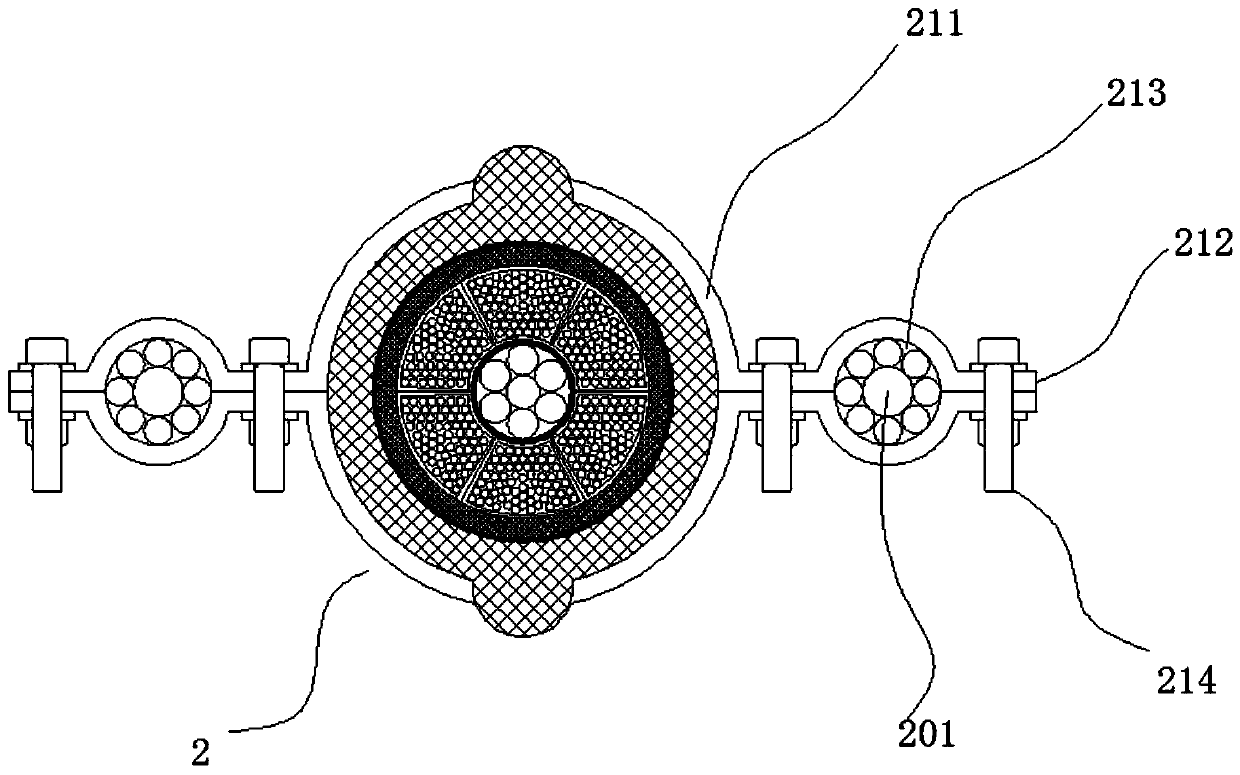
[0026] refer to image 3 and Figure 4 As shown, the difference from Embodiment 1 is that a plurality of connection structures 2 are equidistantly arranged on the outer wall of the sheath 101, and suspension steel cables 201 are fitted between the plurality of connection structures 2, and the suspension The two ends of the steel cable 201 are connected to the iron tower, and the connecting structure 2 includes two upper and lower clamps 211. The two ends of the clamps 211 are extended to form a horizontal part 212. Between the two clamps 211, the horizontal part passes 212 are combined to form a ring body 213, and bolts 214 are fitted between the two clamps 211 through the horizontal part 212, and two bolts 214 are arranged on one side, which are respectively arranged on both sides of the ring body 213 position; the suspension cable 201 passes through the ring body 213 ; the hoop 211 is limited between two adjacent projections 108 . After adopting the above structure, the st...
Embodiment 3
[0028] refer to Figure 5As shown, the difference from Embodiment 1 is that a suspension 3 is mounted on the outer wall of the sheath 101, and the suspension 3 has an annular support portion 301, and the upper end of the support portion 301 The opening is equipped with a first bolt 302, and the first bolt 302 shrinks the support part 301 after being tightened, so that the support part 301 and the sheath 101 are clamped, and the first bolt 302 is located on the support A positioning wheel 303 made of rubber is sheathed on the part inside the part 301, and a first suspension cable 304 is erected between two adjacent iron towers, and the first suspension cable 304 acts on the position of the positioning wheel 303. At the bottom, the positioning wheel 303 has an annular groove 305 for positioning the first suspension cable 304 . The cable is limited by its structure, and the design diameter of the tensile steel cable contained in it cannot be too large, which leads to insufficien...
PUM
 Abstract
Description
Claims
Application Information
 - R&D
- Intellectual Property
- Life Sciences
- Materials
- Tech Scout
- Unparalleled Data Quality
- Higher Quality Content
- 60% Fewer Hallucinations
Browse by: Latest US Patents, China's latest patents, Technical Efficacy Thesaurus, Application Domain, Technology Topic, Popular Technical Reports.
© 2025 PatSnap. All rights reserved.Legal|Privacy policy|Modern Slavery Act Transparency Statement|Sitemap|About US| Contact US: help@patsnap.com


