Long-distance overhead high-tensile-strength cable

A high-strength, long-distance technology, applied in the direction of insulated cables, cables, circuits, etc., can solve problems such as cable breakage, extended distance, and inseparable from iron towers, so as to achieve good structural stability, reduce curvature and bending, and increase The effect of tensile properties

Active Publication Date: 2019-12-03
深圳来事达电线电缆股份有限公司
View PDF4 Cites 0 Cited by
  • Summary
  • Abstract
  • Description
  • Claims
  • Application Information

AI Technical Summary

Problems solved by technology

[0002] The erection of high-altitude cables is inseparable from the support of iron towers. However, the distance between iron towers needs to be strictly controlled. However, in some special areas, the erection of iron towers is more difficult, or the stability after erection is poor.
It will inevitably extend the distance between two iron towers, which leads to a longer length of cable between two adjacent iron towers, resulting in serious sagging in the middle of the cable, and the cable always has a strong pulling force, which is very easy to cause The cable was pulled, affecting power transmission

Method used


Image

  • Long-distance overhead high-tensile-strength cable
  • Long-distance overhead high-tensile-strength cable
  • Long-distance overhead high-tensile-strength cable

Examples


Embodiment 1

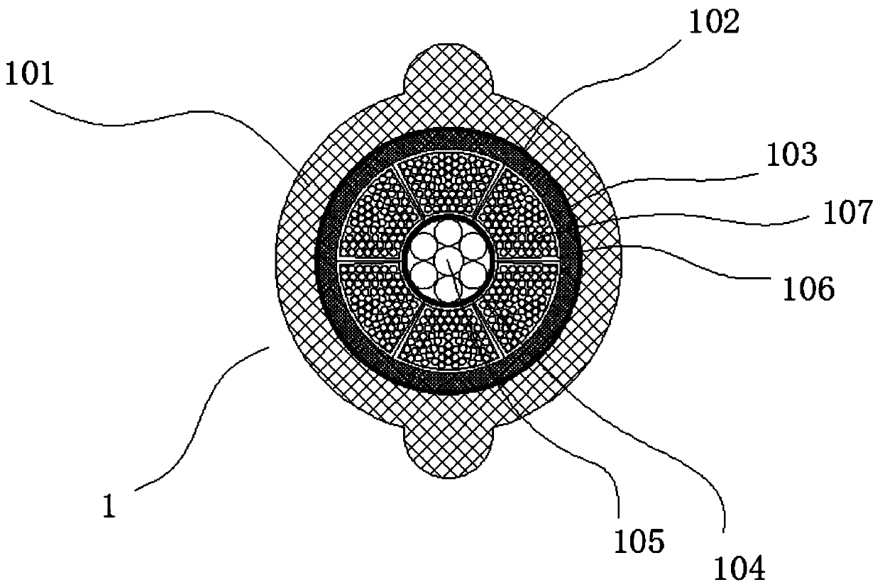
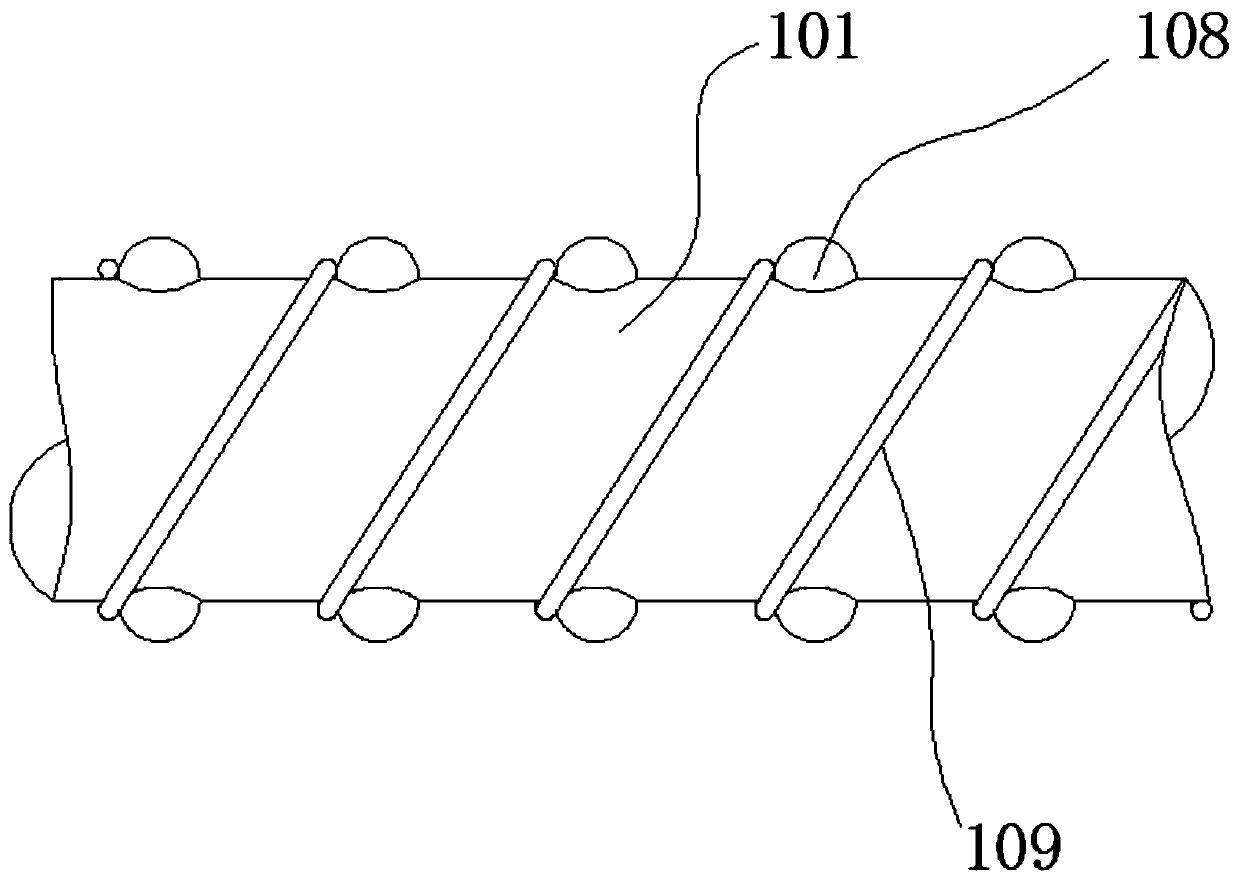
[0024] see figure 1 and figure 2 A long-distance overhead cable with high tensile strength is shown, including a cable body 1, the cable body 1 includes a sheath 101, and a steel strip 102 arranged on the inner layer of the sheath 101, and a The inner lining layer 103 at the inner side of the steel belt 102, and the covering layer 104 arranged at the axis of the inner lining layer 103, a tensile steel cable 105 is arranged in the outer covering layer 104, and the tensile steel cable 105 consists of An axial steel cable and a plurality of peripheral steel cables are formed. The multiple peripheral steel cables are spirally wound around the outer wall of the axial steel cable. An insulating sleeve 106, an aluminum conductor 107 is inserted into the insulating sleeve 106, and two rows of bumps 108 are arranged on the outer wall of the jacket 101, and the bumps are hemispherical. The bumps 108 are respectively arranged on the upper and lower sides of the sheath 101, and a sprin...

Embodiment 2

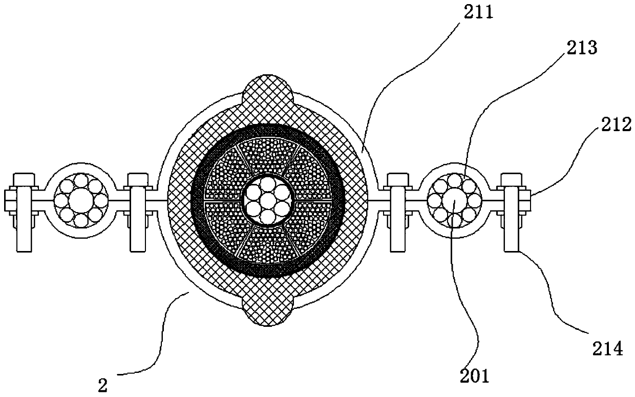
[0026] see image 3 and Figure 4 As shown, the difference from Embodiment 1 is that a plurality of connection structures 2 are arranged at equal distances on the outer wall of the sheath 101, and a suspension steel cable 201 is fitted between the plurality of connection structures 2. Both ends of the steel cable 201 are connected to the iron tower. The connection structure 2 includes two upper and lower clamps 211. The two ends of the clamps 211 are extended to form a horizontal portion 212. Between the two clamps 211, the horizontal portion passes through. 212 are combined to form a ring body 213 , bolts 214 are fitted between the two clamps 211 through the horizontal part 212 , and two bolts 214 are provided on one side, which are respectively arranged on both sides of the ring body 213 position; the suspension cable 201 passes through the ring body 213 ; the clamp 211 is limited between two adjacent protrusions 108 . After the above structure is adopted, the erection sta...

Embodiment 3

[0028] see Figure 5As shown, the difference from Embodiment 1 is that a hanger 3 is assembled on the outer wall of the sheath 101 , and the hanger 3 has an annular support part 301 , and the upper end of the support part 301 is A first bolt 302 is assembled at the opening. After the first bolt 302 is tightened, the support portion 301 is retracted, so that the support portion 301 and the sheath 101 are clamped. The first bolt 302 is located in the support portion. The inner part of the part 301 is covered with a positioning wheel 303 made of rubber material, and a first suspension steel cable 304 is erected between two adjacent iron towers. At the bottom, the positioning wheel 303 has an annular groove 305 for positioning the first suspension cable 304 . The cable is limited by its structure, and the design diameter of the tensile steel cable contained in it cannot be too large, which leads to the insufficient tensile performance of the cable under long-distance span. After...


PUM


Abstract

The invention discloses a long-distance overhead high-tensile-strength cable which comprises a cable body. The cable body comprises a sheath, a steel strip arranged on the inner layer of the sheath, an inner lining layer which is arranged at a position inside the steel strip, and a wrapping layer which is arranged at the axis of the inner lining layer. A tensile steel cable is arranged in the wrapping layer. A number of insulation sleeves are arranged between the wrapping layer and the inner lining layer in the shape of a ring, aluminum conductors are interposed in the insulation sleeves. According to the product, a spring wire is spirally wound on the outside of the sheath; when the cable is bent with curvature, the spring wire can be used to increase the bending strength of the cable toreduce the curvature of the cable; when the curvature of the cable is reduced, the cable's tensile force is reduced, and the tensile performance of the cable is improved; and bumps are arranged on theouter wall of the sheath to effectively space the spring wire, so that the spring wire has better structural stability.

Description

technical field [0001] The invention relates to a long-distance overhead cable with high tensile strength. Background technique [0002] The erection of high-altitude cables is inseparable from the support of the towers. However, the distance between the towers needs to be strictly controlled. However, in some special areas, the erection of the towers is more difficult, or the stability after the erection is poor. It is inevitable that the distance between the two towers will be extended, which leads to a long cable length between two adjacent towers, resulting in serious sagging in the middle of the cable. The cable always has a strong tensile force, which is very easy to cause. Cables are pulled and broken, affecting power transmission. [0003] Based on the above problems, we designed a long-distance overhead cable with high tensile performance that can achieve long-distance span erection. SUMMARY OF THE INVENTION [0004] The technical problem to be solved by the pre...

Claims


Application Information

Patent Timeline
Patent Type & Authority Applications(China)
IPC IPC(8): H01B7/18H01B7/24H01B7/22H01B7/02H01B3/28
CPCH01B3/28H01B7/0258H01B7/1875H01B7/22H01B7/225H01B7/24
Inventor 黄东来
Owner 深圳来事达电线电缆股份有限公司
Why Eureka
Try Eureka