A Vibration Feed Movement Realization Device for Electrolytic Machining

A technology of feeding motion and machining vibration, applied in electric machining equipment, electrochemical machining equipment, accessories, etc., can solve the problems of low efficiency of electrolytic machining and achieve the effect of improving efficiency

Inactive Publication Date: 2020-10-30
HARBIN UNIV OF SCI & TECH
View PDF12 Cites 2 Cited by
  • Summary
  • Abstract
  • Description
  • Claims
  • Application Information

AI Technical Summary

Problems solved by technology

[0003] However, because the traditional feeding mechanism can only realize the feeding movement of the cathode tool, it cannot make the cathode tool vibrate while the cathode tool is performing the feeding movement, so the traditional feeding mechanism has low electrolytic machining efficiency. The problem

Method used


Image

  • A Vibration Feed Movement Realization Device for Electrolytic Machining
  • A Vibration Feed Movement Realization Device for Electrolytic Machining
  • A Vibration Feed Movement Realization Device for Electrolytic Machining

Examples


Embodiment 1

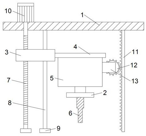
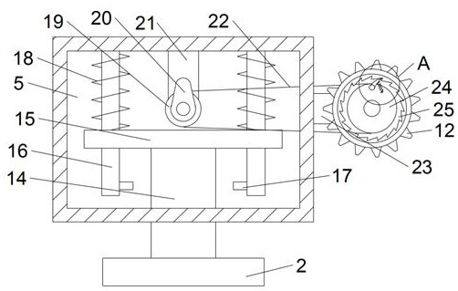
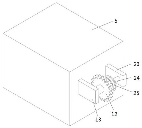
[0024] Refer to attached Figure 1-4 , this embodiment provides a vibration feed movement realization device for electrolytic machining, which includes a fixed plate 1 and a mounting block 2 for installing a cathode tool 6, a slide block 3 is provided slidingly below the fixed plate 1, and the The slider 3 is connected with the feed mechanism which is used to drive the slider 3 to move up and down and has a self-locking function. The slider 3 is provided with a vibration chamber 5, and a movable plate is installed in the vibration chamber 5. 15. The mounting block 2 is arranged at the bottom of the movable plate 15; the movable plate 15 is connected with the vibrating assembly for driving the movable plate 15 to vibrate, and the vibration chamber 5 and the fixed plate 1 are provided with Transmission assembly; when the slider 3 descends, the transmission assembly drives the vibrating assembly to vibrate.

[0025] Specifically, the connecting plate 4 is fixed on the slider 3, ...

Embodiment 2

[0031] Refer to attached Figure 5 , this embodiment is improved on the basis of Embodiment 1, specifically, the bottom of the installation block 2 is provided with a clamping assembly for fixing the cathode tool 6 . Wherein, the clamping assembly includes two sets of positioning blocks 28, the positioning blocks 28 are fixed on the bottom of the installation block 2, and the clamping screws 29 for clamping the cathode tool 6 are threaded on the positioning blocks 28 . When the cathode tool 6 needs to be installed, the cathode tool 6 is first placed between two sets of positioning blocks 28, and then the clamping screws 29 on the two sets of positioning blocks 28 are tightened so that the clamping screw 29 is offset against the cathode tool 6, The fixed installation of the cathode tool 6 can be completed.

[0032] In summary, the embodiment of the present invention arranges the mounting block 2 at the bottom of the movable plate 15, slides the movable plate 15 in the vibrati...


PUM


Abstract

The invention discloses a vibration feed motion realizing device for electrochemical machining and belongs to the technical field of electrochemical machining. The vibration feed motion realizing device comprises a fixed plate and a mounting block, wherein a sliding block is arranged below the fixed plate in a sling manner and is connected with a feed mechanism; a vibration chamber is arranged onthe sliding block; a moving plate is movably arranged in the vibration chamber; the mounting block is arranged at the bottom of the moving plate; the moving plate is connected with a vibration component; and a driving component is arranged between the vibration chamber and the fixed plate. According to the vibration feed motion realizing device, the mounting block is arranged at the bottom of themoving plate, the moving plate is arranged in the vibration chamber in a sliding manner and the vibration chamber is internally provided with the vibration component, so that the driving component candrive the moving plate to do up-down reciprocating motion while the vibration chamber descends, further a cathode tool does vibrating motion while doing feed motion, and eventually the efficiency ofelectrochemical machining can be improved.

Description

technical field [0001] The invention relates to the technical field of electrolytic machining, in particular to an electrolytic machining vibration feed movement realization device. Background technique [0002] Electrolytic machining refers to a process that uses the principle of anodic dissolution to process metal workpieces. In the process of electrolytic machining, the cathode tool is often installed on the feed mechanism, and then the cathode tool is driven by the feed mechanism to perform a feed movement, so as to facilitate the electrolytic machining of the anode workpiece. [0003] However, because the traditional feeding mechanism can only realize the feeding movement of the cathode tool, it cannot make the cathode tool vibrate while the cathode tool is performing the feeding movement, so the traditional feeding mechanism has low electrolytic machining efficiency. The problem. Contents of the invention [0004] The object of the present invention is to provide a...

Claims


Application Information

Patent Timeline
Patent Type & Authority Patents(China)
IPC IPC(8): B23H3/00B23H11/00
CPCB23H3/00B23H11/00
Inventor 李兆龙曹炳任葛江华王亚萍杨晓冬
Owner HARBIN UNIV OF SCI & TECH
Why Eureka
Try Eureka