
A kind of micro-hole electrolytic machining machine vision positioning and navigation method

A technology of positioning, navigation and machine vision, applied in electric processing equipment, electrochemical processing equipment, metal processing equipment, etc., can solve the problem of no discovery, and achieve the effect of reducing human error and improving efficiency

Inactive Publication Date: 2018-07-20
XI AN JIAOTONG UNIV
View PDF6 Cites 0 Cited by
  • Summary
  • Abstract
  • Description
  • Claims
  • Application Information

AI Technical Summary

Problems solved by technology

After reviewing domestic and foreign documents, no publications have been found that combine visual measurement technology with micropore electrolytic machining.

Method used


Image

  • A kind of micro-hole electrolytic machining machine vision positioning and navigation method
  • A kind of micro-hole electrolytic machining machine vision positioning and navigation method
  • A kind of micro-hole electrolytic machining machine vision positioning and navigation method

Examples


Embodiment Construction

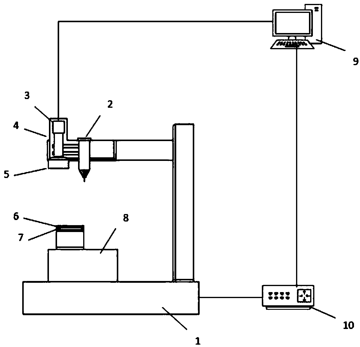
[0027] The present invention will be described in detail below in conjunction with the accompanying drawings.

[0028] A micropore electrolytic machining machine vision positioning and navigation method, comprising the following steps:

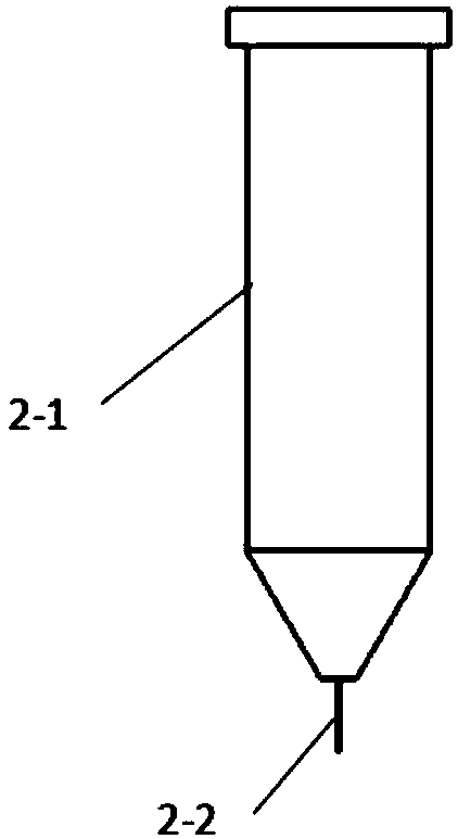
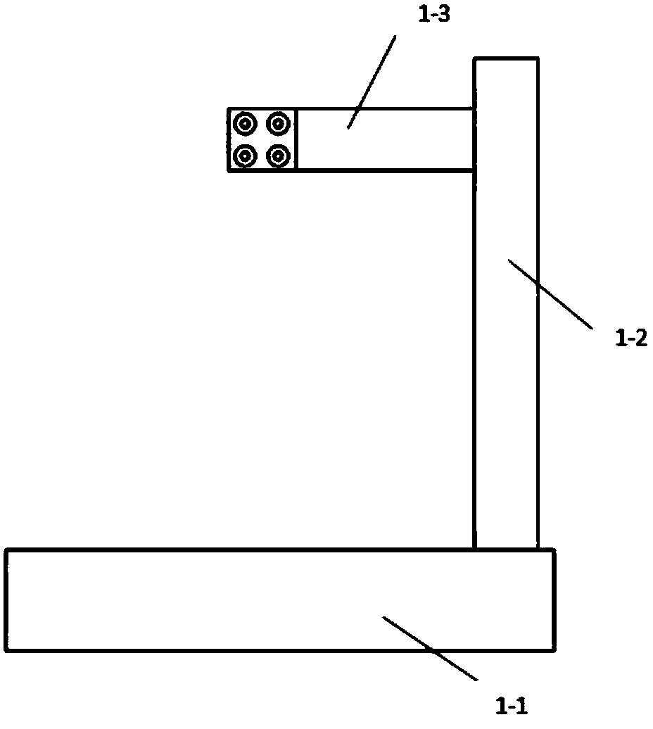
[0029] Step 1: Refer to figure 1 , figure 2 , image 3 and Figure 4 , using a visual device to install the target 7 on the pad 8 through the second clamp 6;

[0030] Step 2: Turn on the camera 3, adjust the camera 3 to a corresponding position, focus, and determine the optimal imaging distance between the camera 3 and the surface of the target 7;

[0031] Step 3: Calibrate the pixel equivalent of the visual device, and use the target 7 to calibrate the pixel equivalent r: First, the visual device collects the image of the target 7 for image processing, and obtains the pixel coordinate values ​​of all calibration points on the target 7, such as Figure 5 As shown, in the four areas of the target image plane in the camera field of view, s...


PUM


Abstract

A microporous electrolytic machining machine vision positioning and navigation method. First, the vision device is used to install the target on the pad, and then the pixel equivalent of the vision device is calibrated, and then the electrode wire is used as the origin. The guide rail is the x and y axes of the coordinate system, establish the electrode wire coordinate system, calibrate the coordinate system of the vision device, and then calibrate the coordinate system offset of the vision device, and then place the workpiece to be processed on the fixture, and pass the vision device When the microhole to be processed is detected, the computer calculates the coordinates x and y of its center through the image processing program, and calculates the displacement information, and sends the displacement information to the control cabinet control workbench, so that the microhole to be processed and the electrode wire are aligned , electrolytically process the microhole, and then carry out the electrolytic machining of the next microhole. The present invention uses vision to detect the center of the microhole and completes the alignment of its electrode wire, which can greatly improve the accuracy and efficiency of electrolytic machining.

Description

technical field [0001] The invention relates to the field of advanced manufacturing technology, in particular to a machine vision positioning and navigation method for micropore electrolytic processing. Background technique [0002] With the gradual development of precision, high performance and miniaturization of products, components with micro-sized structures have been widely used in many fields. Laser-electrolytic composite machining is used for the micro-hole machining of aerospace engine turbine blades, especially group hole machining. The laser pre-processes the micro-holes, and then electrolytically performs secondary processing. The electrolytic processing is mainly to remove the recast layer and improve the processing quality of the micro-holes. When electrolytic secondary machining of micro-holes, the electrode wire needs to be aligned with the center of the micro-hole first, the electrode wire is inserted into the micro-hole, and the electrode wire and the workp...

Claims


Application Information

Patent Timeline
Patent Type & Authority Patents(China)
IPC IPC(8): B23H3/00B23H11/00
CPCB23H3/00B23H11/00
Inventor 王恪典霍权贾国华
Owner XI AN JIAOTONG UNIV
Learn More