Grinding head and grinding tool

A grinding head and clamping body technology, which is used in the manufacture of tools, grinding machine parts, grinding/polishing equipment, etc., can solve problems such as scrapping of grinding heads, low efficiency of grinding operations, and thread wear.

Pending Publication Date: 2019-12-06
SUZHOU MICROPORT ORTHORECON CO LTD
View PDF0 Cites 2 Cited by
  • Summary
  • Abstract
  • Description
  • Claims
  • Application Information

AI Technical Summary

Problems solved by technology

[0003] When performing grinding operations, the grinding head is set on the base of the abrasive tool, and when replacing the sandpaper ring, it is necessary to manually loosen the self-tightening screw, then replace a new sandpaper ring, and then manually tighten the self-tightening screw. The replacement process takes about 5 minutes, and the service life of each sandpaper ring is about 10 minutes. inefficiency
Moreover, in practice, there is a lot of dust in the environment of the grinding operation. In order to protect the operator, when replacing the sandpaper ring, the grinding head is generally disassembled from the base and transferred to a relatively clean environment before performing the sandpaper ring. Replacement, and finally the grinding head is installed on the base, which further increases the workload of the operator
In addition, when replacing the sandpaper ring, it is necessary to repeatedly tighten and loosen the self-tightening screw, which will easily cause wear and tear on the inner thread of the threaded hole used to install the self-tightening screw, which will cause the grinding head to be scrapped

Method used


Image

  • Grinding head and grinding tool
  • Grinding head and grinding tool

Examples


Embodiment Construction

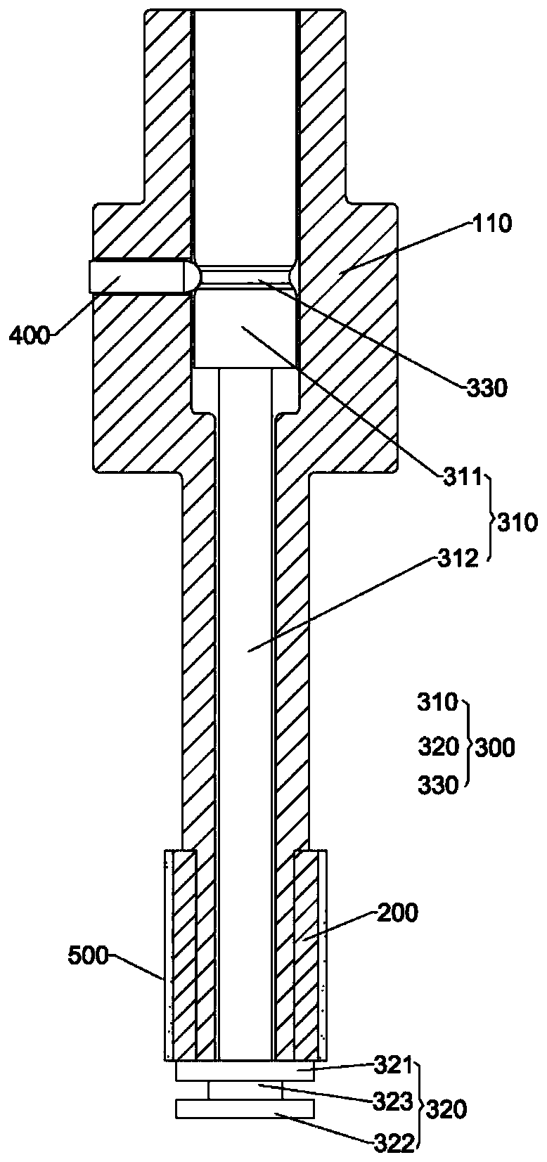
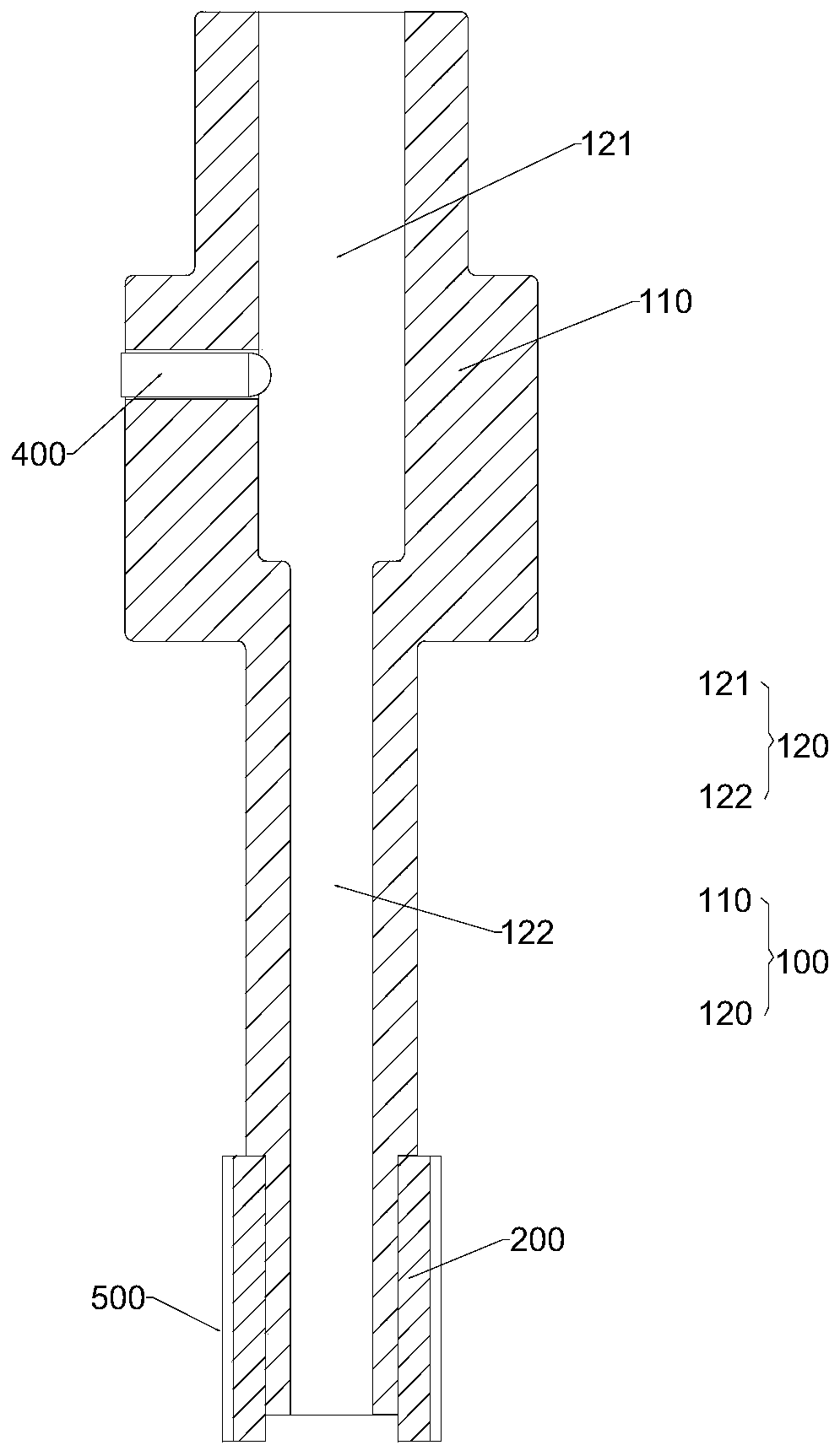
[0035] In order to make the purpose, advantages and features of the present invention clearer, the embodiments of the present invention will be further described in detail below in conjunction with the accompanying drawings. It should be noted that all the drawings are in a very simplified form and use imprecise scales, and are only used to facilitate and clearly assist the purpose of illustrating the embodiments of the present invention.

[0036] As used in this specification and the appended claims, the singular forms "a," "an," and "the" include plural referents unless the content clearly dictates otherwise. As used in this specification and the appended claims, the term "or" is generally used in its sense including "and / or", unless the content clearly indicates otherwise, and the terms "installed", "connected" 2. "Connection" should be understood in a broad sense, for example, it can be a fixed connection, a detachable connection, or an integral connection. It can be a me...


PUM


Abstract

The invention relates to a grinding head and a grinding tool. The grinding head comprises a clamping body, an elastic supporting ring, a core bar and a locking mechanism. The clamping body is providedwith the elastic supporting ring, the core bar is arranged in the clamping body and used for abutting against and pushing the elastic supporting ring so that the elastic supporting ring can be expanded in the radial direction, and the locking mechanism is arranged on the clamping body and locks the core bar through the elastic action so that the elastic supporting ring can be kept in an expansionstate. Elastic force generated by the locking mechanism is utilized for fixing the position of the core bar, elastic force is overcome so that the core bar can be made to move, the relative positionbetween the core bar and the elastic supporting ring is adjusted, and replacement of an abrasive paper ring can be achieved. Control over the relative position between the core bar and the elastic supporting ring through manual screw screwing is not needed, and the labor intensity of manual replacement of the abrasive paper ring is lowered.

Description

technical field [0001] The invention relates to the technical field of mechanical processing, in particular to a grinding head and a grinding tool. Background technique [0002] At present, the grinding head equipped with the grinding gun includes a rotating shaft, an elastic grinding core, a sandpaper ring and a self-tightening screw. The shaft is set, and the sandpaper ring is set on the elastic grinding core. When the self-tightening screw is tightened, the self-tightening screw exerts an axial force on the elastic grinding core, so that the elastic grinding core expands in the radial direction while shortening in the axial direction, so that the elastic grinding core The frictional force between the core and the sandpaper ring increases, and like this, when the rotating shaft drives the elastic grinding core to rotate, the sandpaper ring can rotate with the elastic grinding core. [0003] When performing grinding operations, the grinding head is set on the base of the ...

Claims


Application Information

Patent Timeline
Patent Type & Authority Applications(China)
IPC IPC(8): B24B41/04
CPCB24B41/04
Inventor 金承高陈福兵俞天白
Owner SUZHOU MICROPORT ORTHORECON CO LTD
Why Eureka
Try Eureka