
Electroencephalogram signal acquisition device and method

An EEG signal and signal acquisition technology, which is applied in medical science, diagnosis, diagnostic recording/measurement, etc., can solve problems such as increasing electrode impedance, increasing the distance between electrodes and nerve cells, and low degree of freedom in signal decoding, so as to improve work efficiency. The effect of duration

Active Publication Date: 2021-03-30
FIRST HOSPITAL AFFILIATED TO GENERAL HOSPITAL OF PLA
View PDF6 Cites 6 Cited by
  • Summary
  • Abstract
  • Description
  • Claims
  • Application Information

AI Technical Summary

Problems solved by technology

On the one hand, for the electrodes implanted in the brain dura mater, the brain tissue will produce a certain immune rejection reaction. After the electrodes are inserted into the brain tissue, the glial cells in the brain will gradually wrap the electrode collection end, which not only enlarges the electrode At the same time, it also insulates the electrodes and increases the electrode impedance, so that the electrical signal will gradually become weak until it cannot be collected; on the other hand, for the ECoG acquisition method, due to the weak EEG signal, the signal spatial resolution and signal The noise ratio is relatively low, and the degree of freedom of signal decoding is not high
These problems make the brain-computer interface research encounter bottlenecks in the development and hinder the in-depth and practical progress of the research. Therefore, it is an important task to provide an EEG signal acquisition device and method that can not only collect long-term security but also provide high signal-to-noise ratio. Problems urgently needed to be solved by field technicians

Method used


Image

  • Electroencephalogram signal acquisition device and method
  • Electroencephalogram signal acquisition device and method
  • Electroencephalogram signal acquisition device and method

Examples


Embodiment Construction

[0039] The following will clearly and completely describe the technical solutions in the embodiments of the present invention with reference to the accompanying drawings in the embodiments of the present invention. Obviously, the described embodiments are only some, not all, embodiments of the present invention. Based on the embodiments of the present invention, all other embodiments obtained by persons of ordinary skill in the art without making creative efforts belong to the protection scope of the present invention.

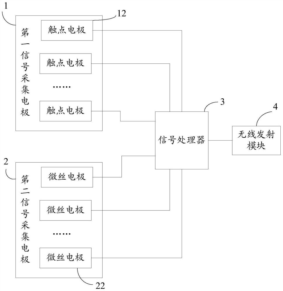
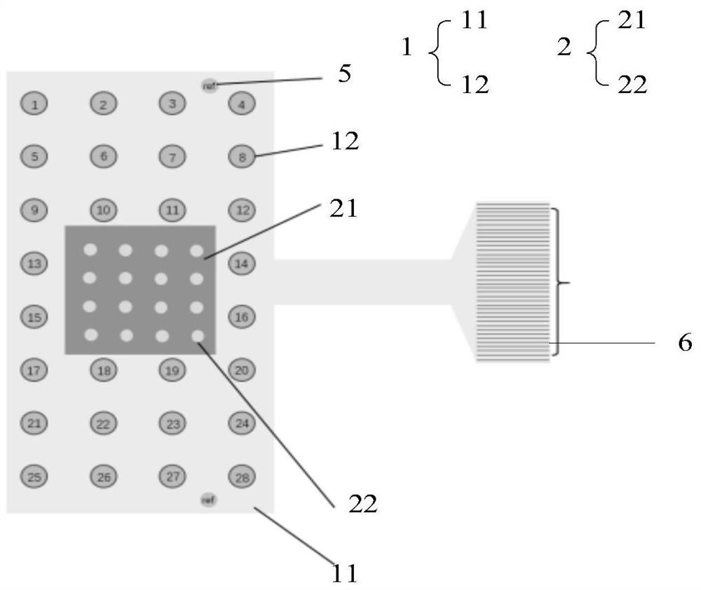
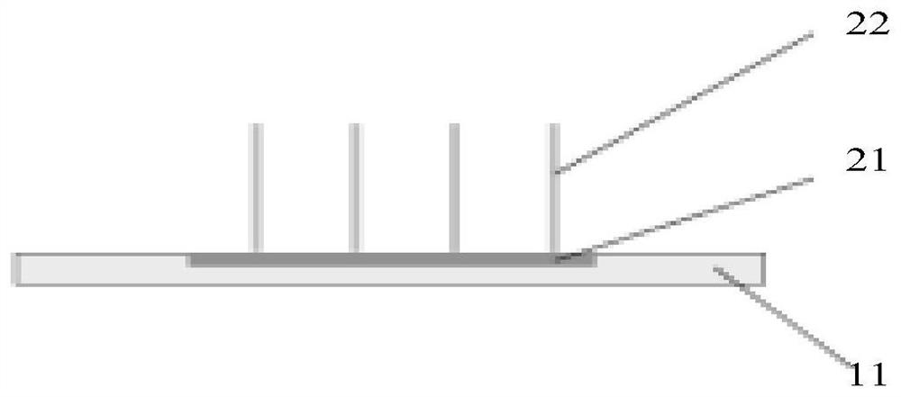
[0040] like Figure 1-3 As shown, the embodiment of the present invention discloses an EEG signal acquisition device, including: a first signal acquisition electrode 1, a second signal acquisition electrode 2, a signal processor 3 and a wireless transmission module 4; the first signal acquisition electrode 1, The second signal collecting electrode 2 and the wireless transmitting module 4 are respectively electrically connected to the signal processor 3; the wi...


PUM


Abstract

The invention discloses an electroencephalogram signal acquisition device and method. The electroencephalogram signal acquisition device comprises a first signal acquisition electrode, a second signalacquisition electrode, a signal processor and a wireless transmitting module, the first signal acquisition electrode, the second signal acquisition electrode and the wireless transmitting module areelectrically connected with the signal processor. The wireless transmitting module is in wireless communication with a brain-computer interface; the first signal acquisition electrode is used for acquiring a Spike signal; the second signal acquisition electrode is used for acquiring an ECoG signal; the signal processor is used for processing and converting the Spike signal and the ECoG signal; thewireless transmitting module is used for transmitting the processed and converted Spike signal and ECoG signal to the brain-computer interface; the brain-computer interface is used for training the Spike signal and the ECoG signal and establishing the relevance between the Spike signal and the ECoG signal of the receptor under different actions. According to the invention, electroencephalogram signals can be safely collected for a long time, and a high signal-to-noise ratio can be provided.

Description

technical field [0001] The present invention relates to the technical field of medical equipment, and more specifically relates to a device and method for collecting electroencephalogram signals. Background technique [0002] Over the years, patients with spinal cord injury and epilepsy have suffered from insufficient exercise capacity. Although some clinical research progress has been made in this type of disease, there is still a big gap from the real recovery of exercise capacity. In this regard, researchers have carried out research on it in the field of engineering, and achieved good results. Among them, brain-computer interface technology (brain-computer interface), as an emerging human-computer interaction method, has become a current international research hotspot. Brain-computer interface refers to the channel that directly realizes the transmission of information between the brain and the outside world without relying on nerve channels such as peripheral nerves an...

Claims


Application Information

Patent Timeline
Patent Type & Authority Applications(China)
IPC IPC(8): A61B5/369A61B5/291A61B5/263A61B5/00
CPCA61B5/7267A61B5/725
Inventor 李晓寇建阁石岩王娜王一轩任帅
Owner FIRST HOSPITAL AFFILIATED TO GENERAL HOSPITAL OF PLA
Learn More