Sorgho stalk section head subsection cutting equipment

A technology of joint head and sweet rod, applied in the direction of metal processing, etc., can solve the problems of different cutting length, easy to be cut by sickle, and more labor consumption.

Active Publication Date: 2019-12-06
台州来智科技有限公司
View PDF6 Cites 0 Cited by
  • Summary
  • Abstract
  • Description
  • Claims
  • Application Information

AI Technical Summary

Problems solved by technology

[0003] In order to overcome the shortcomings of manually cutting the sweet bar joint head, it takes a lot of manpower, the length of the cutting is different, and it is easy to be cut by the sickle during the cutting process. The technical problem to be solved is: to provide a method that can save Segmental resection equipment for sweet bar joints with manpower, consistent resection length, and no cutting by the blade during the resection process

Method used


Image

  • Sorgho stalk section head subsection cutting equipment
  • Sorgho stalk section head subsection cutting equipment
  • Sorgho stalk section head subsection cutting equipment

Examples


Embodiment 1

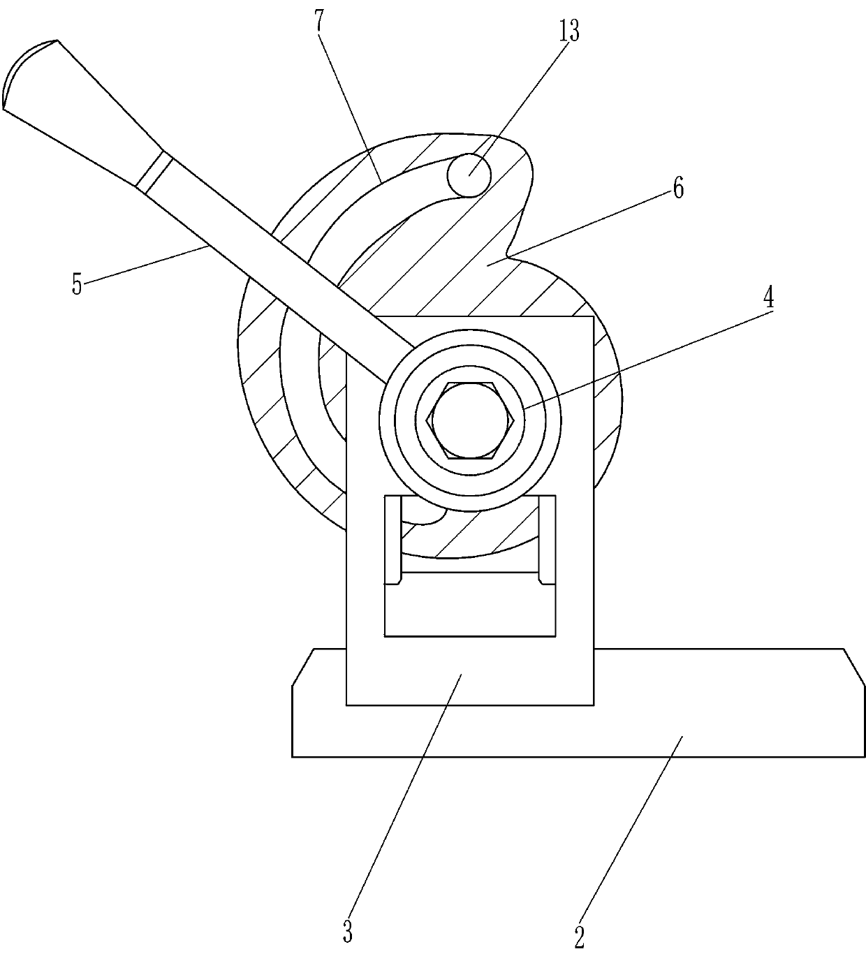
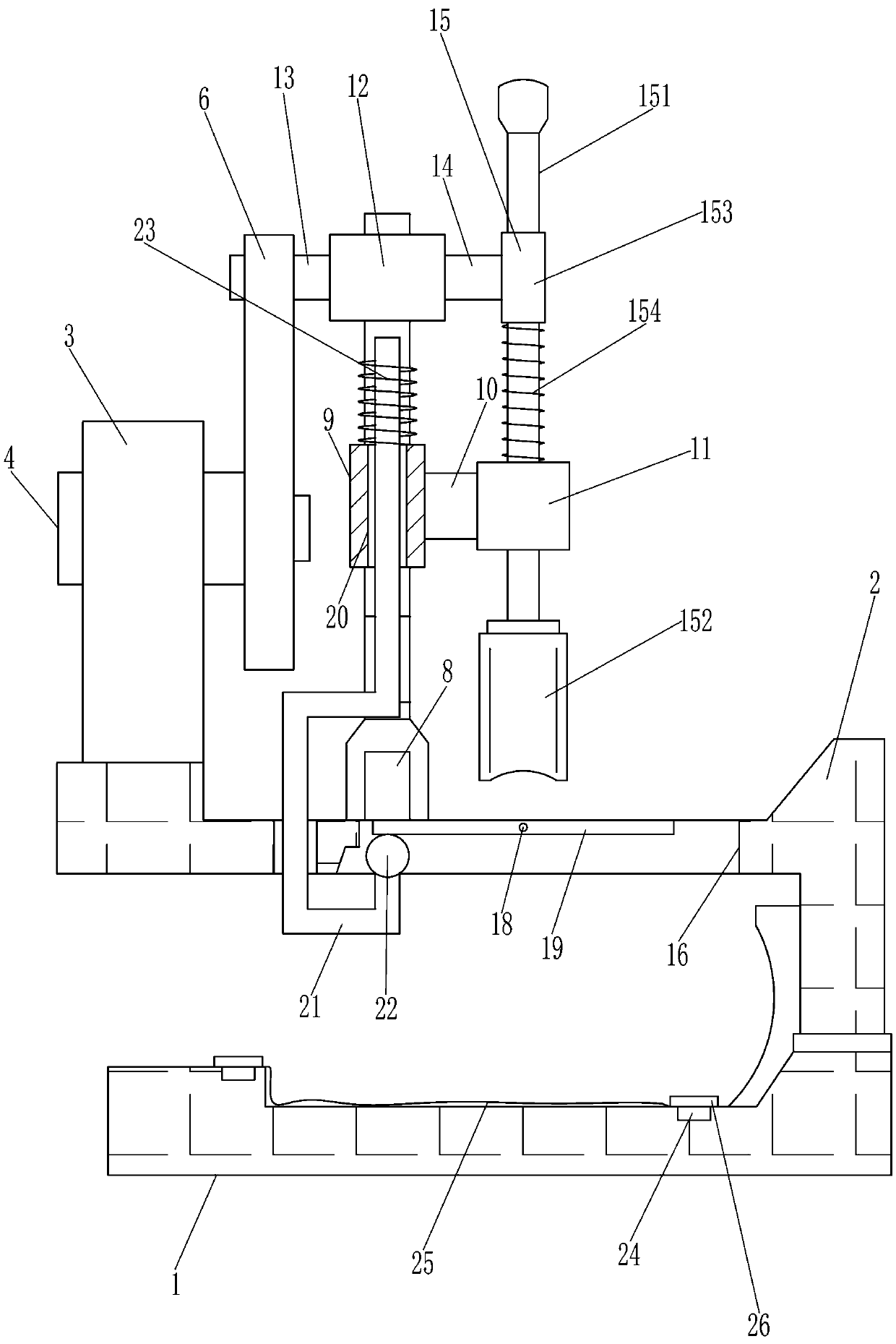
[0017] A kind of sweet bar section head section excision equipment, such as Figure 1-3 As shown, it includes a base 1, a mounting seat 2, a mounting frame 3, a first rotating shaft 4, a rotating rod 5, a cam disc 6, an L-shaped sliding rod 8, a fixed sleeve 9, a first support rod 10, a guide sleeve 11, a sliding Cover 12, the first push rod 13, the second push rod 14 and the cutting device 15, the top right side of the base 1 is provided with the mounting seat 2, the base 1 is connected with the mounting seat 2 by welding, and the left side of the mounting seat 2 is provided Mounting frame 3 is arranged, and the middle rotating type of mounting frame 3 tops is provided with first rotating shaft 4, and the left part of first rotating shaft 4 is provided with rotating rod 5, and the right part of first rotating shaft 4 is provided with cam disc 6, and arc is arranged on cam disc 6. Shaped groove 7, the left side of the top of the mounting base 2 is provided with an L-shaped sli...

Embodiment 2

[0019] A kind of sweet bar section head section excision equipment, such as Figure 1-3 As shown, it includes a base 1, a mounting seat 2, a mounting frame 3, a first rotating shaft 4, a rotating rod 5, a cam disc 6, an L-shaped sliding rod 8, a fixed sleeve 9, a first support rod 10, a guide sleeve 11, a sliding Cover 12, the first push rod 13, the second push rod 14 and the cutting device 15, the right side of the base 1 top is provided with the mounting seat 2, the left side of the mounting seat 2 top is provided with the mounting frame 3, and the middle rotating type of the mounting frame 3 top is provided. There is a first rotating shaft 4, the left part of the first rotating shaft 4 is provided with a rotating rod 5, the right part of the first rotating shaft 4 is provided with a cam disc 6, an arc-shaped groove 7 is opened on the cam disc 6, and a L Type slide bar 8, L-type slide bar 8 is positioned at the right side of mounting frame 3, L-shaped slide bar 8 middle part...

Embodiment 3

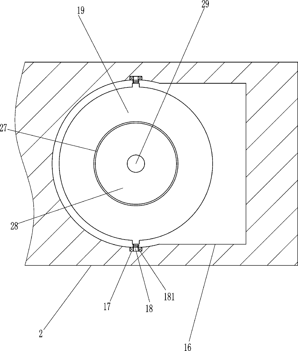
[0022] A kind of sweet bar section head section excision equipment, such as Figure 1-4 As shown, it includes a base 1, a mounting seat 2, a mounting frame 3, a first rotating shaft 4, a rotating rod 5, a cam disc 6, an L-shaped sliding rod 8, a fixed sleeve 9, a first support rod 10, a guide sleeve 11, a sliding Cover 12, the first push rod 13, the second push rod 14 and the cutting device 15, the right side of the base 1 top is provided with the mounting seat 2, the left side of the mounting seat 2 top is provided with the mounting frame 3, and the middle rotating type of the mounting frame 3 top is provided. There is a first rotating shaft 4, the left part of the first rotating shaft 4 is provided with a rotating rod 5, the right part of the first rotating shaft 4 is provided with a cam disc 6, an arc-shaped groove 7 is opened on the cam disc 6, and a L Type slide bar 8, L-type slide bar 8 is positioned at the right side of mounting frame 3, L-shaped slide bar 8 middle part...


PUM


Abstract

The invention relates to subsection cutting equipment, in particular to sorgho stalk section head subsection cutting equipment. The technical purpose is to provide the sorgho stalk section head subsection cutting equipment which can save labor, achieve a consistent cutting length, and guarantee that people are unlikely to get cut by blades. According to the technical scheme, the sorgho stalk section head subsection cutting equipment comprises a base, a mounting base, a mounting frame, a first rotary shaft and the like; the mounting base is arranged at the right side of the top of the base, andthe mounting frame is arranged at the left side of the top of the mounting base. According to the sorgho stalk section head subsection cutting equipment, by pulling a first push rod to rotate, the first push rod rotates and drives a cam disc to rotate, then the cam disc rotates and drives the first push rod to move downwards through an arc groove, thus a guide rod is driven to move downwards, andthen drives a cutting head to move downwards, and in this way, the cutting head conducts subsection cutting on sorgho stalk section heads; through the cooperation of a rubber ball and a first circular disc, the sorgho stalk section heads on the first circular disc fall onto the base through an opening, and in this way, a user does not need to manually clean away the sorgho stalk section heads.

Description

technical field [0001] The present invention relates to a segmental cutting device, in particular to a segmental cutting device for sweet bar joints. Background technique [0002] Sweet stalk, also known as sugar sorghum, is a kind of sugar crop, and it is also an excellent feed crop and energy crop. It has original fragrance and sweet taste, and is the best raw material for green drinks. Because the skin of sweet stalk is relatively hard and sharp, Therefore, when eating sweet stalks, it is necessary to manually peel the skins. Before peeling, the joints of the sweet stalks need to be cut off. The usual segmental excision of the sweet stalks is to manually use a sickle to separate the sweet stalks. When the pole joint head is cut off, it takes a lot of manpower, and the length of the cut is different, and it is easy to be cut by the sickle during the cut. Contents of the invention [0003] In order to overcome the shortcomings of manually cutting the sweet bar joint head...

Claims


Application Information

Patent Timeline
Patent Type & Authority Applications(China)
IPC IPC(8): B26D1/08B26D5/16B26D7/00
CPCB26D1/08B26D5/16B26D7/00B26D2210/02
Inventor 许东
Owner 台州来智科技有限公司
Why Eureka
Try Eureka