Quick disassembly and assembly of building formwork frame

A building formwork and fast technology, which is applied in construction, building structure, connection parts of formwork/formwork/work frame, etc., can solve the problems of low construction efficiency, time-consuming building formwork, inconvenient dismantling of building formwork, etc. The effect of easy installation

Active Publication Date: 2021-08-17
宜昌楚鑫建设有限责任公司
View PDF8 Cites 0 Cited by
  • Summary
  • Abstract
  • Description
  • Claims
  • Application Information

AI Technical Summary

Problems solved by technology

[0006] The main purpose of the present invention is to provide a quick disassembly and assembly building formwork frame, which solves the problem that it takes a long time to build the building formwork, and it is also very inconvenient when disassembling the building formwork. After the concrete slurry solidifies, the formwork is pried up, resulting in a Damage, low construction efficiency

Method used


Image

  • Quick disassembly and assembly of building formwork frame
  • Quick disassembly and assembly of building formwork frame
  • Quick disassembly and assembly of building formwork frame

Examples


Embodiment 1

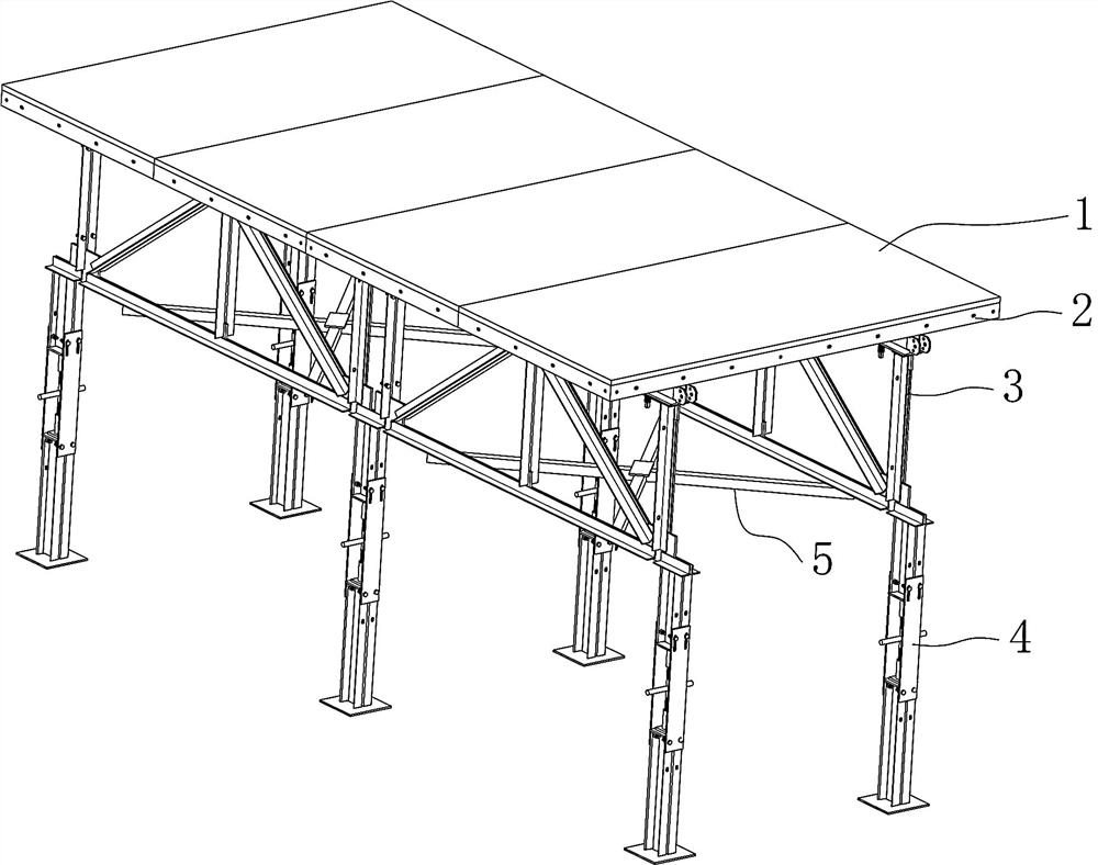
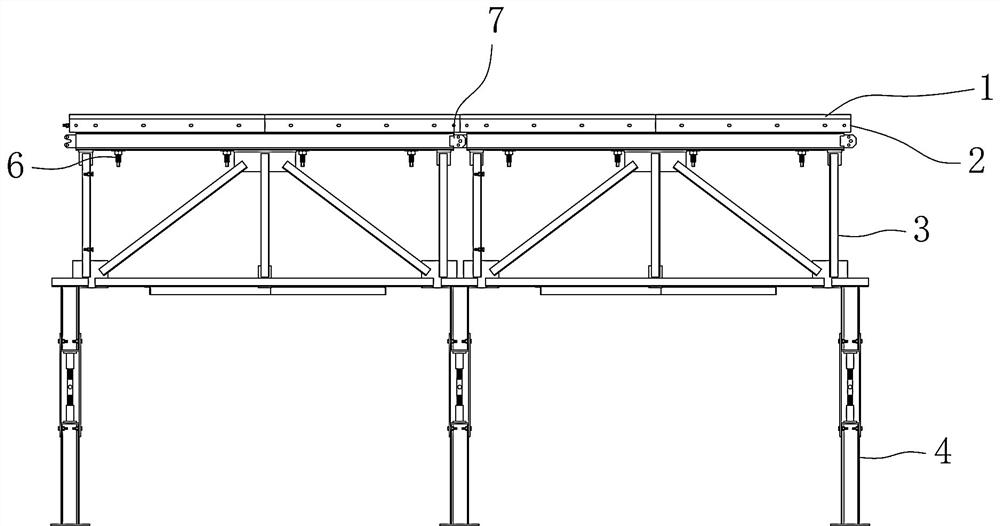
[0043] Such as Figure 1~17 As shown, a quick disassembly and assembly building formwork frame includes a formwork 2, a formwork 1 is arranged above the formwork 2, and a support frame 3 composed of a plurality of connecting rods 302 is provided below the formwork 2. The support frame 3 and the formwork 2 A plurality of parallel beams 301 are arranged between them, and the template 1 is fixed on the formwork 2 through a tensioning mechanism 6. Threaded connection, the other end passes through the formwork 2 and the parallel beam 301, and is reversely locked by the lock nut 603, a limit plate 602 is provided between the lock nut 603 and the beam 301, and the end of the lock nut 603 A locking part 604 is provided, and a plurality of bottom support rods 4 are arranged below the support frame 3, and the bottom support rods 4 include a first support foot 402 and a second support foot 404, between the first support foot 402 and the second support foot 404 An adjustment rod 8 is pro...

Embodiment 2

[0057] Further illustrate in conjunction with embodiment 1, as Figure 1~17 As shown, when the quick detachable building formwork frame is in use, a large number of connecting rods 302 , mounting plates 303 , beams 301 , bottom support rods 4 and formwork 1 are transported from the factory.

[0058] After arriving at the construction site, the connecting rod 302, the mounting plate 303 and the beam 301 are installed as Figure 6 In the structure of the supporting frame 3 shown, the bottoms of two side-by-side supporting frames 3 are connected by a stabilizing frame 5 .

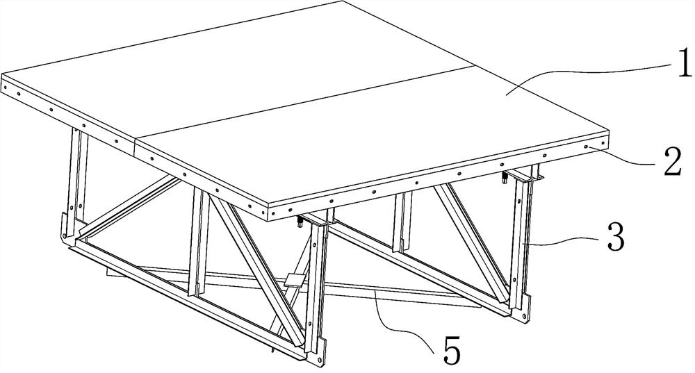
[0059] After the supporting frame 3 is installed, the formwork 2 is installed on the beam 301, the template 1 is spread on the formwork 2, and the template 1 is locked on the supporting frame 3 by the tension rod 601 and the locking nut 603. Support frame 3 forms an integral body with formwork 2 and template 1 like this, as image 3 As shown, two templates 1 can be installed on one whole, the size of one tem...


PUM


Abstract

A quick disassembly and assembly formwork frame. There is a formwork on the top of the formwork, and a support frame composed of a plurality of connecting rods below the formwork. There are multiple parallel beams between the support frame and the formwork. The formwork is pulled The tightening mechanism is fixed on the formwork, one end of the tension rod is threadedly connected with the formwork, the other end passes through the formwork and the parallel beams, and is reversely locked by the lock nut. There are multiple bottom support rods under the support frame. The support rod includes a first support foot and a second support foot, an adjustment rod is arranged between the first support foot and the second support foot, the two ends of the adjustment rod are threadedly connected with the first support foot and the second support foot, and the two ends of the adjustment rod The rotation direction of the thread is opposite. The support frame is used to form a whole with the formwork and the formwork. The bottom support rod is used to support the whole. The overall removal is faster and more convenient. The adjustment rod makes the formwork fall off, implementing the non-damage connection and removal of the formwork.

Description

technical field [0001] The invention relates to the construction field, in particular to a quick disassembly and assembly building formwork frame. Background technique [0002] The building formwork is a temporary support structure, which is manufactured according to the design requirements, so that the concrete structure and components are formed according to the specified position and geometric size, maintain their correct position, and bear the self-weight of the building formwork and the external load acting on it. The purpose of formwork engineering is to ensure the quality of concrete engineering and construction safety, speed up the construction progress and reduce engineering costs. The building formwork structure used in the construction of cast-in-place concrete structures is mainly composed of three parts: panels, support structures and connectors. The panel is the load-bearing slab that directly contacts the freshly poured concrete; the support structure is a te...

Claims


Application Information

Patent Timeline
Patent Type & Authority Patents(China)
IPC IPC(8): E04G9/02E04G17/00
CPCE04G9/02E04G17/00
Inventor 周成进陈华松
Owner 宜昌楚鑫建设有限责任公司
Why Eureka
Try Eureka