Regenerative control hydraulic system

A hydraulic system, regeneration control technology, applied in the direction of fluid pressure actuating device, earth mover/shovel, servo motor, etc. Reduced fuel consumption and pressure loss, good responsiveness, simplified regeneration and regeneration cut-off control effects

Pending Publication Date: 2019-12-06
JIANGSU HENGLI HYDRAULIC TECH CO LTD
View PDF0 Cites 3 Cited by
  • Summary
  • Abstract
  • Description
  • Claims
  • Application Information

AI Technical Summary

Problems solved by technology

[0004] In order to solve the technical problems of the regeneration control hydraulic system in the prior art, such as complex regeneration and regeneration cut-off co

Method used


Image

  • Regenerative control hydraulic system
  • Regenerative control hydraulic system
  • Regenerative control hydraulic system

Examples


Embodiment Construction

[0028] The following will clearly and completely describe the technical solutions in the embodiments of the present invention with reference to the accompanying drawings in the embodiments of the present invention. Obviously, the described embodiments are only some, not all, embodiments of the present invention. The following description of at least one exemplary embodiment is merely illustrative in nature and in no way taken as limiting the invention, its application or uses. Based on the embodiments of the present invention, all other embodiments obtained by persons of ordinary skill in the art without creative efforts fall within the protection scope of the present invention.

[0029]It should be noted that the terminology used here is only for describing specific implementations, and is not intended to limit the exemplary implementations according to the present application. As used herein, unless the context clearly dictates otherwise, the singular is intended to include ...


PUM


Abstract

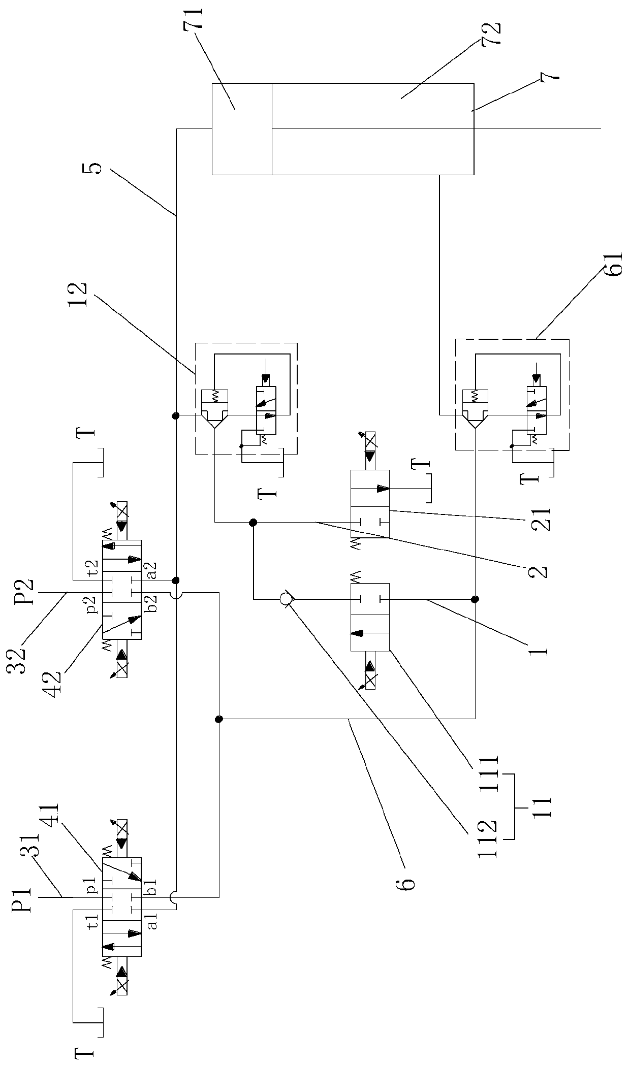
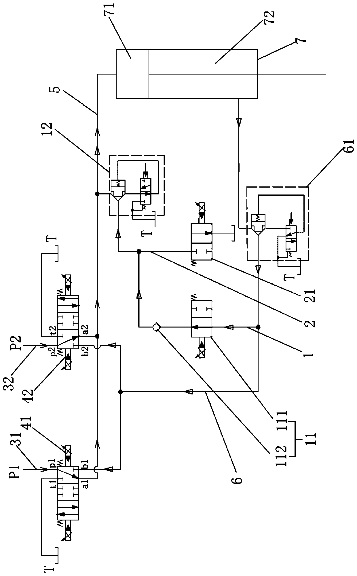
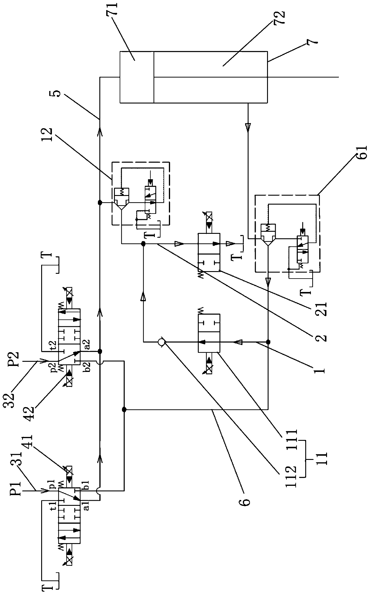
The invention relates to a hydraulic system of a working machine, and particularly relates to a regenerative control hydraulic system. The regenerative control hydraulic system includes at least one hydraulic pump which ejects working oil, an actuator which works by means of supply of the working oil from the at least one hydraulic pump, a regenerative oil path for sending return oil as regenerative oil to a negative-pressure cavity of the actuator and a regenerative cut-off oil path. The return oil is the working oil discharged from the actuator, the regenerative oil path is provided with a regenerative valve and a control valve III, the control valve III is used for controlling the regenerative oil to enter the negative-pressure cavity of the actuator when a working device contracts back, or the oil is discharged from the actuator to the regenerative cut-off oil path when the working device outwards sways; and the regenerative cut-off oil path sends the regenerative oil of the regenerative valve or the oil discharged from the actuator to other destinations, and the regenerative cut-off oil path is provided on a regenerative cut-off valve. The technical problems of the complexityof regeneration and regenerative cut-off control structures, low regulation and slow response in a regenerative control cut-off hydraulic system in the prior art are solved.

Description

technical field [0001] The invention relates to a working machine hydraulic system, in particular to a regenerative control hydraulic system. Background technique [0002] Among the current construction machinery, the use of excavators has been greatly promoted and applied, and its fuel consumption, work efficiency and ease of operation are the main concerns of various main engine manufacturing companies, R&D institutions and customers. The working device of the excavator is composed of main parts such as the boom, the stick, the bucket, and the hydraulic pipeline of the working device including the boom cylinder, the stick cylinder, and the bucket cylinder. The stick is an important part of the working device of the excavator. Components, the reasonable setting of its hydraulic system is of great significance to the working performance of the excavator. [0003] In the prior art, the operation efficiency of the stick is generally improved by combining two hydraulic pumps t...

Claims


Application Information

Patent Timeline
IPC IPC(8): F15B11/08F15B13/04E02F9/20E02F9/22
CPCE02F9/20E02F9/22E02F9/2232E02F9/2267E02F9/2292F15B11/08F15B13/0401F15B2211/20576F15B2211/405
Inventor 汪立平黄国和贾靖哈良刘红光韩俊翔翟莉
Owner JIANGSU HENGLI HYDRAULIC TECH CO LTD
Why Eureka
Try Eureka