Image capturing apparatus and method for controlling the same

Inactive Publication Date: 2019-07-25
CANON KK
View PDF13 Cites 1 Cited by
  • Summary
  • Abstract
  • Description
  • Claims
  • Application Information

AI Technical Summary

Benefits of technology

[0007]The present invention has been made in consideration of the above situation, and enab

Problems solved by technology

Thus, if the EC device is used as a variable ND filter, there is a problem in that it takes time to achieve a desired light attenuation ratio, an instruction from a user or a camera is delayed, and a response to a change in luminance

Method used


Image

  • Image capturing apparatus and method for controlling the same
  • Image capturing apparatus and method for controlling the same
  • Image capturing apparatus and method for controlling the same

Examples


Example

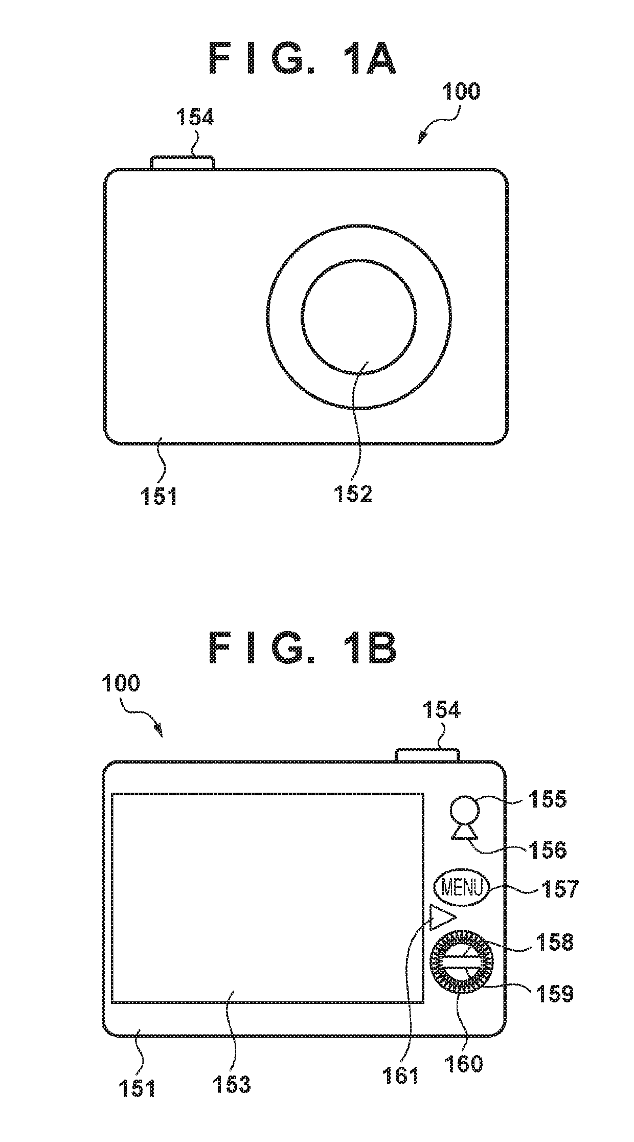
[0032]A first embodiment of the present invention will be described. FIGS. 1A and 1B are external views of an image capturing apparatus 100 in the first embodiment, FIG. 1A showing a front view of the image capturing apparatus 100, and FIG. 1B showing a rear view of the image capturing apparatus 100. The image capturing apparatus 100 includes an image capturing apparatus main body 151 that internally houses an image sensor and a shutter apparatus, and an imaging optical system 152 that has a diaphragm therein. Also, a display unit 153 for displaying imaging information or video and various switches are arranged on its back surface and upper surface.

[0033]The image capturing apparatus 100 includes, as the switches, a switch 154 that is mainly used to capture still images, a switch 155 that is a button for starting or stopping capturing of a moving image, and an imaging mode selection lever 156 for selecting an imaging mode. Furthermore, the image capturing apparatus 100 includes a me...

Example

Second Embodiment

[0114]Next, a second embodiment of the present invention will be described. Although the EC material is used as the light-amount control element 185A in the above-described first embodiment, an electric light-amount control element in which guest-host liquid crystal containing a dichroic dye is used may also be used.

[0115]FIGS. 9A to 9C are schematic cross-sectional views of an electric light-amount control element 185B in which guest-host liquid crystal containing the above-described dichroic dye is used. The light-amount control element 185B has a configuration in which a space between a transparent substrate 201a and a transparent substrate 201b that are disposed facing to each other is filled with a mixture obtained by mixing liquid crystal molecules 210 and a dichroic dye 211 together, and its surrounding is sealed by a sealing material 203. Inner surfaces of the transparent substrates 201a and 201b in the sealed space are respectively provided with a transpare...

Example

Third Embodiment

[0131]Next, a third embodiment of the present invention will be described. FIG. 11 is an external view of an image capturing apparatus 300 in the third embodiment. In FIG. 11, an exterior portion of the image capturing apparatus 300 is provided with an imaging button 302 that is an operation member for starting and stopping imaging, and an ND effect setting unit 303 that is an operation member for adjusting the exposure amount of the luminous flux for imaging a subject that is incident from an imaging optical system 301 at the time of imaging. A user can set the exposure amount of the luminous flux imaging a subject by operating the ND effect setting unit 303 so as to cause a light-amount control element, which will be described later, to function. Also, the image capturing apparatus 300 is provided with a display unit 304 that displays an image of the subject and imaging conditions at the time of imaging. As will be described later, an imaging preview image or a cap...


PUM


Abstract

An image capturing apparatus comprising: a light-amount control element that changes a transmittance of light; an image sensor that photoelectrically converts light that has passed through the light-amount control element and changes an exposure amount by intermittently accumulating charges in a predetermined cycle in each frame; and a controller that controls the transmittance of the light-amount control element and the exposure amount controlled by the image sensor so as to achieve a preset target exposure amount.

Description

BACKGROUND OF THE INVENTIONField of the Invention[0001]The present invention relates to an image capturing apparatus and a method for controlling the same, and more specifically to an image capturing apparatus that has a light-amount control element configured to change the transmittance of light, and a method for controlling the same.Description of the Related Art[0002]A technique for attenuating the light intensity of a subject using a light attenuation member such as an ND filter in a conventional image capturing apparatus is known. For example, by selecting an appropriate light attenuation ratio according to the brightness of an imaging scene using variable ND filters with different density related to the light attenuation ratio, an image (or video) with brightness desired by a user can be acquired.[0003]An optical variable light attenuation means such as a liquid crystal element or an element in which an inorganic electrochromic (EC) thin film (referred to as “EC device” herein...

Claims


Application Information

Patent Timeline
IPC IPC(8): H04N5/235H04N5/225H04N5/232
CPCH04N5/2353H04N5/2256H04N5/232H04N2005/44565H04N23/60H04N23/73H04N23/75H04N25/771H04N21/47H04N21/6547H04N23/56
Inventor UCHIDA, TAKESHINOTO, GORO
Owner CANON KK
Why Eureka
Try Eureka