Laser transmitting antenna

A technology of laser emission and antenna, which is applied in the field of optics, can solve the problems of large volume of laser emission antenna and achieve the effect of small volume, large numerical aperture and reduced focal length

Active Publication Date: 2019-12-06
WUHAN UNIV
View PDF6 Cites 3 Cited by
  • Summary
  • Abstract
  • Description
  • Claims
  • Application Information

AI Technical Summary

Problems solved by technology

[0004] The embodiment of the present application solves the problem of the large volume of the laser transmitting antenna in the prior art by providing a laser transmitting antenna

Method used


Image

  • Laser transmitting antenna
  • Laser transmitting antenna
  • Laser transmitting antenna

Examples


Embodiment Construction

[0025] In order to better understand the above-mentioned technical solution, the above-mentioned technical solution will be described in detail below in conjunction with the accompanying drawings and specific implementation methods.

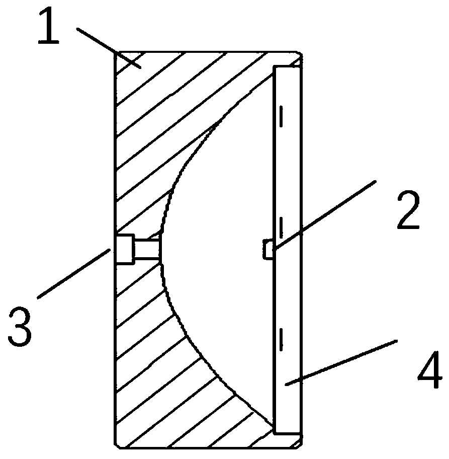
[0026] This embodiment provides a laser transmitting antenna, such as figure 1 As shown, it includes: a parabolic mirror 1, a metamaterial mirror 2, an incident window 3, and an exit window 4; the metamaterial mirror 2 is confocal with the parabolic mirror 1, and the incident window 3 is embedded in the In the parabolic mirror 1 , the base layer of the metamaterial mirror 2 serves as the exit window 4 .

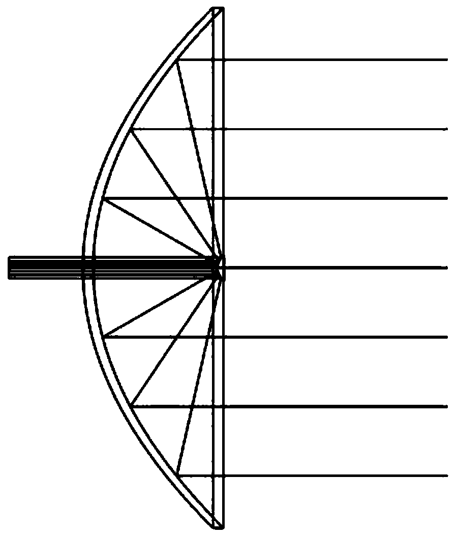
[0027] After the light beam enters the laser transmitting antenna through the incident window 3, the incident light beam is diverged by using the metamaterial reflector 2, and the divergent light beam is expanded during propagation, reflected and collimated on the surface of the parabolic reflector 1, Finally exit through the exit window 4 .

...


PUM


Abstract

The invention belongs to the technical field of optics, and discloses a laser transmitting antenna, which comprises a metamaterial reflector, a parabolic reflector, an incident window and an emergentwindow. The metamaterial reflector and the parabolic reflector share the same focal point; the incident window is embedded in the parabolic reflector; and a substrate layer of the metamaterial reflector serves as an emergent window. The problem that in the prior art, the size of a laser transmitting antenna is large is solved, the overall axial length of the transmitting antenna can be shortened,and a smaller size is achieved.

Description

technical field [0001] The invention relates to the field of optical technology, in particular to a laser emitting antenna. Background technique [0002] The beam divergence angle of lidar is one of the key parameters that determine the performance of radar ranging. Therefore, it is usually necessary to compress the beam divergence angle by using a laser transmitting antenna in a lidar system. Compressing the divergence angle can not only increase the energy density of the spot, enhance the detection ability of the laser radar, reduce the size of the far-field spot of the beam, improve the spatial resolution of the laser radar, but also reduce the field of view of the receiving system, thereby reducing background noise, Improve radar detection probability and ranging accuracy. [0003] Existing laser transmitting antennas for beam expansion are generally composed of a concave lens and a convex lens, and its divergence angle compression capability is determined by the ratio ...

Claims


Application Information

Patent Timeline
Patent Type & Authority Applications(China)
IPC IPC(8): G01S7/481G01S17/08G02B5/10
CPCG01S7/4814G01S17/08G02B5/10
Inventor 李松曾昊旻周鑫张智宇
Owner WUHAN UNIV
Why Eureka
Try Eureka