Method for automatically planning optimal layout flow chart

An automatic planning and flow chart technology, applied in 2D image generation, image data processing, instruments, etc., can solve problems such as adding extra work, reducing work efficiency, crossing, etc., to achieve beautiful layout, efficient layout, and uniform relative distance. Effect

Pending Publication Date: 2019-12-06
成都深思科技有限公司
View PDF7 Cites 1 Cited by
  • Summary
  • Abstract
  • Description
  • Claims
  • Application Information

AI Technical Summary

Problems solved by technology

However, when we use existing workflow development tools to edit workflows, we often spend a lot of time adjusting the layout of workflow nodes and connecting lines. Due to the randomness of manually dragging process workflow nodes, often

Method used


Image

  • Method for automatically planning optimal layout flow chart
  • Method for automatically planning optimal layout flow chart

Examples


Example Embodiment

[0039] The present invention will be further explained below in conjunction with the drawings:

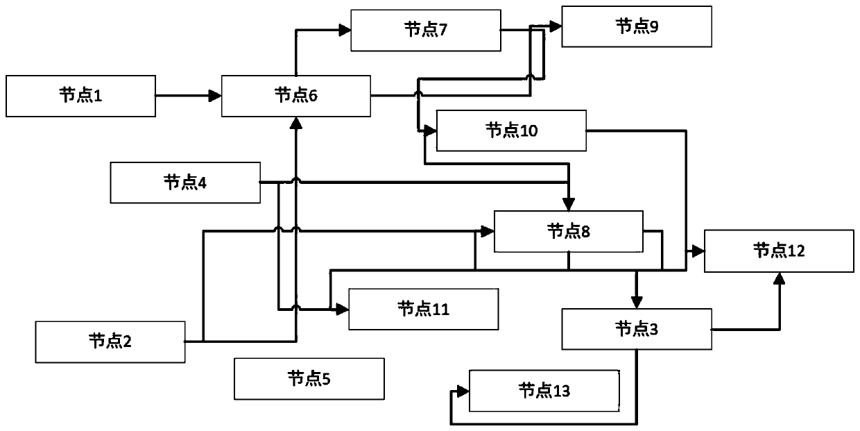
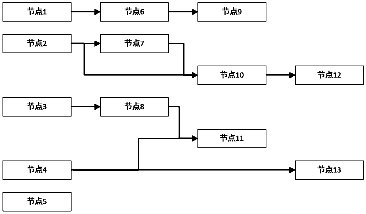
[0040] A method for automatically planning an optimal layout flow chart, including the following steps:

[0041] Step 1: Set the maximum width or maximum height of the workflow node (choose one), and set the interval width and height of the node;

[0042] Step 2: Get all the workflow nodes that have been configured in the current workflow tool, and include the parent-child relationship between the nodes;

[0043] Step 3: Traverse all the workflow nodes, get the name of each node, and then use the C# built-in method FormattedText to get the pixel length and pixel height needed to display the complete node name without wrapping, and finally get the length and Maximum height

[0044] Step 4: Get the width and height of the node during automatic layout;

[0045] (1) If the user sets the maximum width, first determine whether the maximum width is greater than the maximum length obtained in step 3...


PUM


Abstract

The invention discloses a method for automatically planning an optimal layout flow chart. Calling can be carried out at any stage of user configuration. After calling, the workflow nodes on the interface can adapt to the size according to the node name content, and the workflow nodes are added from left to right according to the sequence of adding the workflow nodes by the user. Layout is automatically carried out according to the relation from top to bottom. The father-child level relation is embodied through automatic line feed, the logic relation between workflow nodes can be seen at a glance, connecting lines between the workflow nodes are calculated through the method, and the situation that the workflow nodes are traversed is avoided.

Description

Technical field [0001] The invention relates to the technical field of flow chart layout, in particular to a method for automatically planning an optimal layout flow chart. Background technique [0002] With the development of graphical technology, when people express their ideas or describe a complex business logic, they tend to use relatively intuitive flowcharts or model diagrams to replace the original lengthy plain text instructions. This not only makes the problem description itself vivid and interesting, but also helps to reflect the author's own thinking process and the relationship between the various sub-modules. However, when we use existing workflow development tools for workflow editing, we often spend a lot of time adjusting the layout of workflow nodes and connecting lines. Due to the arbitrariness of manually dragging workflow nodes, we often There will be situations where workflow nodes overlap, connection lines overlap, cross or even cross workflow nodes, and h...

Claims


Application Information

Patent Timeline
IPC IPC(8): G06T11/00
CPCG06T11/00Y02P90/30
Inventor 王炜王文武邓金祥代先勇刘洋谷峰曾海刚
Owner 成都深思科技有限公司
Why Eureka
Try Eureka