Cathode movement push rod mechanism

A technology of push rod mechanism and cathode movement, which is applied in the electrolysis process, electrolysis components, casting and molding equipment, etc., can solve the problems of difficult to guarantee accuracy, numerous processing procedures, and large floor space, so as to reduce the failure rate, ensure accuracy, The effect of reducing the footprint

Active Publication Date: 2011-07-20
WUXI XINGYI INTELLIGENT ENVIRONMENT EQUIP CO LTD
View PDF4 Cites 3 Cited by
  • Summary
  • Abstract
  • Description
  • Claims
  • Application Information

AI Technical Summary

Problems solved by technology

In the whole process, there are problems such as large waste of materials, various processing procedures, high labor costs, and difficulty in ensuring accuracy.
In addition, the electroplating equipment is relatively large, has many pipelines, and occupies a large area. The movement of the cathode needs to be linked, and there are horizontal and vertical transmissions, which must occupy a certain amount of space.

Method used


Image

  • Cathode movement push rod mechanism
  • Cathode movement push rod mechanism

Examples


Embodiment Construction

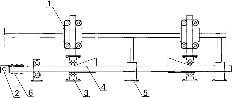
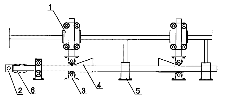
[0010] Such as figure 1 As shown, the cathode moving push rod mechanism of the present invention includes a pulley frame 1, a connecting rod 2, a bearing seat 3, a slanting block 4 and a hollow column support 5, and the connecting rod 2 is installed on a square tube that moves vertically The pulley frame 1 is provided with a slanted block 4 directly below the rollers at the bottom of the pulley frame 1, and a bearing seat 3 is provided on one side of the slanted block 4; a hollow column support 5 is provided between the two slanted blocks 4, and one end of the connecting rod 2 It is fixed on the H-shaped steel frame 6 by bolts to ensure the horizontal accuracy of the connecting rod 2 mechanism, and then the tooling is used to ensure the vertical accuracy of the pulley frame 1 component. When working, the connecting rod 2 can reciprocate in the horizontal direction, and the inclined block 4 can be used to push the square tube in the vertical direction, thereby driving the catho...


PUM


Abstract

The invention relates to a cathode movement push rod mechanism. The mechanism comprises pulley frames, a connecting rod, bearing seats, oblique blocks and a hollow upright post support, wherein square tubes which do vertical movement above the connecting rod are provided with the pulley frames; an oblique block is arranged under a roller positioned at the bottom of each pulley frame; one side of each oblique block is provided with a bearing seat; the hollow upright post support is arranged between the two oblique blocks; and one end of the connecting rod is fixed on an H-shaped steel frame through a bolt. The mechanism has the advantages that: the original form is improved into a mold opening casting form, so that material cost and labor cost can be saved, the accuracy of equipment is ensured, personal errors and errors caused by welding deformation are reduced, the accuracy of vertical movement on the two sides of a cathode rod is ensured, the failure rate of the equipment is reduced, and the utilization rate of the equipment and the qualification rate of products are improved; and the occupied area of cathode movement is smaller than that in the prior art, and at least one half of space in the horizontal direction is saved, so that pipelines can be arranged in order, parts are standardized, the equipment is convenient to maintain and replace, and the whole layout is attractive.

Description

technical field [0001] The invention relates to the technical field of electroplating and casting equipment, in particular to a cathode moving push rod mechanism. Background technique [0002] The cathode moving link mechanism is generally used in the electroplating process mechanism of electroplating equipment. Generally, all parts are cut with steel plates, then processed, drilled, and finally welded and assembled. In the whole process, there are problems such as large waste of materials, various processing procedures, high labor costs, and difficulty in ensuring accuracy. In addition, the electroplating equipment is relatively large, has many pipelines, and occupies a large area. The movement of the cathode needs to be linked, and there are horizontal and vertical transmissions, which must occupy a certain amount of space. Contents of the invention [0003] In view of the above defects, the purpose of the present invention is to provide a cathode moving push rod mechan...

Claims


Application Information

Patent Timeline
Patent Type & Authority Applications(China)
IPC IPC(8): C25D17/00B22C9/06
Inventor 匡优新
Owner WUXI XINGYI INTELLIGENT ENVIRONMENT EQUIP CO LTD
Why Eureka
Try Eureka