Upside step type poultry carcass precooler set

A step-type, pre-cooler technology, applied in the direction of coolers, carcass cooling, cold storage, etc., can solve the problems of not too small drop, overall height increase, waste of electric energy, etc., to reduce the degree of pollution and reduce operating costs , The effect of saving cold source energy

Active Publication Date: 2011-06-15
JILIN SSK MASCH&ELECTRON CO LTD
View PDF6 Cites 4 Cited by
  • Summary
  • Abstract
  • Description
  • Claims
  • Application Information

AI Technical Summary

Problems solved by technology

[0003] This method of arranging the pre-cooling units has the following disadvantages: First, there is a drop distance between the pre-cooling machines, and the drop cannot be too small, otherwise, the poultry carcass is not conducive to sliding into the next pre-cooling machine
The larger the processing capacity, the more the number of pre-cooling machines, the greater the cumulative drop distance, the higher the roof of the pre-cooling workshop, the more waste of space, the greater the investment in civil engineering, and the increase in cooling loss
Second, due to the high height of the previous pre-cooler, the water cannot naturally flow from the latter pre-cooler to the previous pre-cooler for utilization, and the available overflow water will flow away in vain
If the water is used, water pumps must be used, which wastes electric energy and increases costs
Second, due to the drop between the pre-coolers, the outriggers of the first pre-cooler are higher, resulting in an increase in its overall height, which brings inconvenience to manufacturing, transportation and installation
It’s just that these patents are technical disclosures on the cooling effect of a single unit, cooling water circulation, and shell shape, and do not mention the technology of the arrangement of pre-cooling units

Method used


Image

  • Upside step type poultry carcass precooler set
  • Upside step type poultry carcass precooler set
  • Upside step type poultry carcass precooler set

Examples


Embodiment Construction

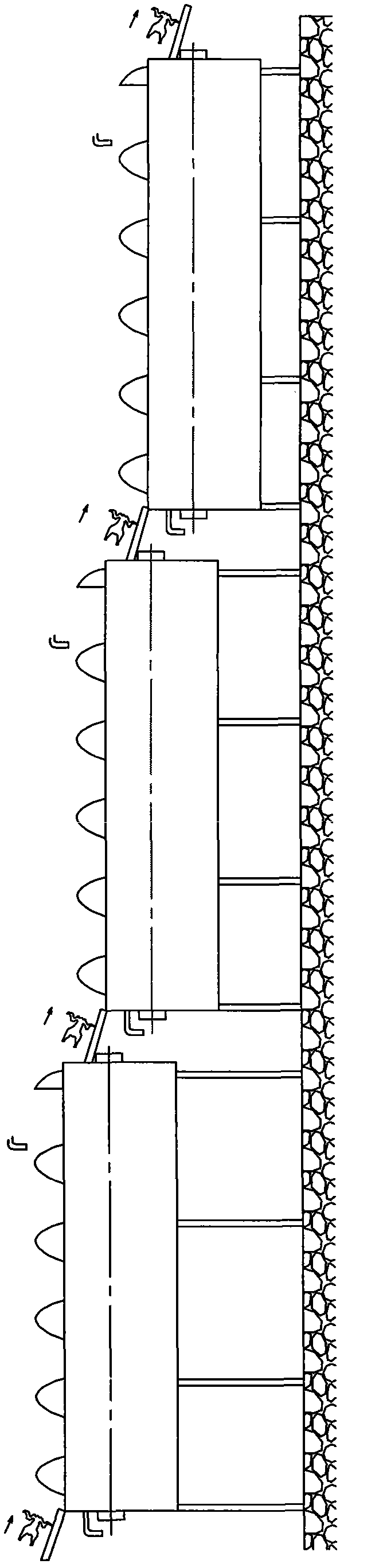
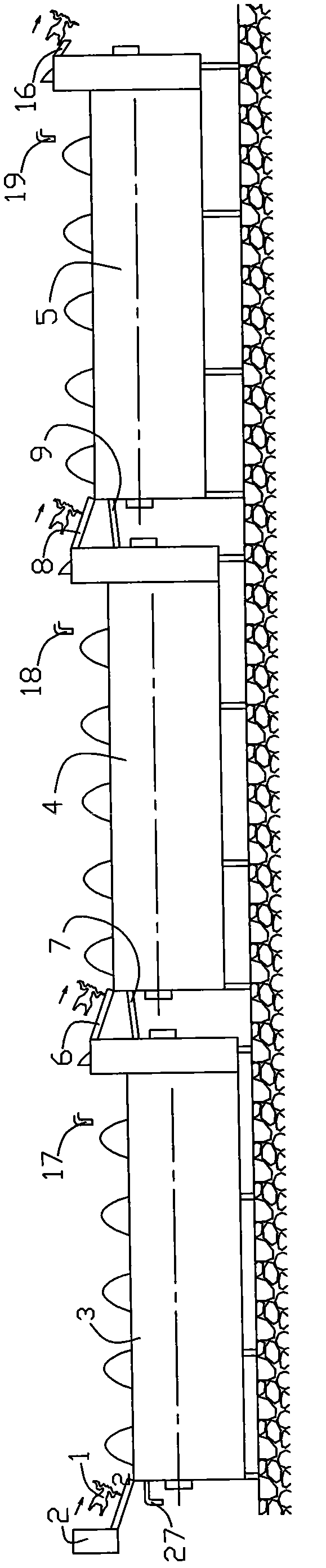
[0025] The pre-cooling unit is composed of multiple single pre-cooling machines arranged in series, and the number of pre-cooling machines can be determined according to the needs. like figure 2 Shown is a three-unit unit: the poultry carcass 1 is unloaded from the equipment 2 of the previous process, and passes through the spiral precooler 3, the precooler 4 and the precooler 5 in turn. These three pre-coolers are arranged in the form of upper steps. That is to say, the first pre-cooler 3, the second pre-cooler 4, and the third pre-cooler 5 rise successively. A chute 6, a water tank 7, a chute 8 and a water tank 9 are connected between the precoolers.

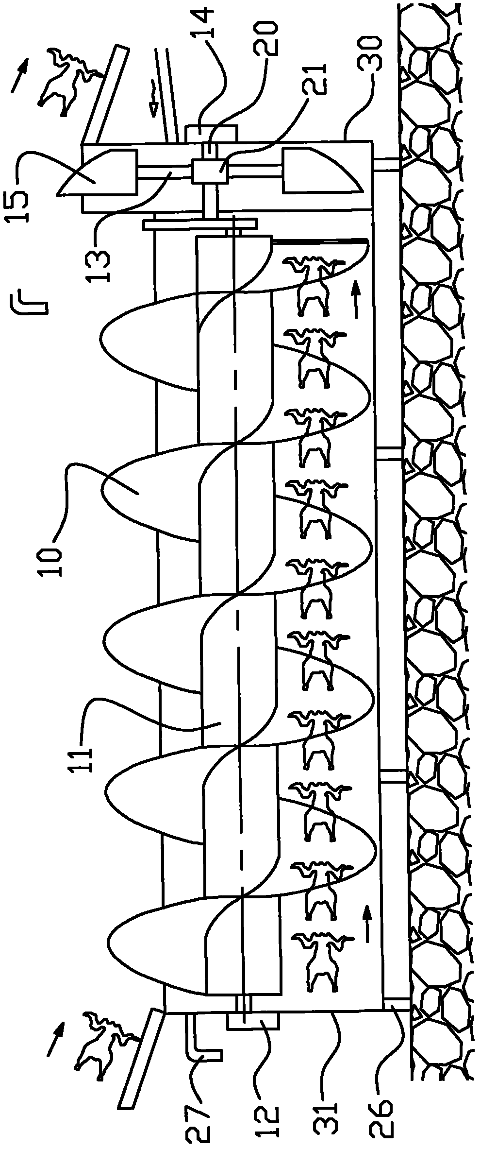
[0026] like image 3 As shown, each precooler is provided with a screw propeller composed of blades 10 and a shaft 11, and the shaft 11 is driven to rotate by a driving device 12. The poultry carcass outlet end is provided with the poultry carcass of high outlet and turns over the mechanism, turns over the mechanism by th...


PUM


Abstract

The invention belongs to the technical field of poultry slaughtering processing and in particular relates to an upside step type precooler set. The pre cooling machine set is formed by serially connecting and arranging a plurality of single precoolers, wherein each precooler is arranged in the manner of gradually rising upside step type, i.e. each precooler can be arranged in the manner of progressive rise along the direction where poultry carcass passes through; a poultry carcass out-turning mechanism with a high outlet is arranged at a discharging end in each precooler; a discharging end plate is provided with a high position discharging outlet edge; and water channels communicated with each other are arranged among the precoolers. Water in the precooler of the next stage can be ensured to flow into the precooler of the previous stage only by increasing a few heights and can progressively flow to the first precooler of a precooling step where poultry carcasses are introduced, therefore, the energy consumption is greatly reduced and water resources are greatly saved, the roof of a shed is not required to be too high, and the civil engineering investment is reduced.

Description

technical field [0001] The invention belongs to the technical field of poultry slaughtering and processing, and in particular relates to a step-up precooling unit. Background technique [0002] In the process of factory poultry slaughtering and processing, most poultry carcasses need to be divided before they can be packaged and put into storage. It takes a certain amount of time to complete the cutting process. Because the temperature of the poultry carcass just removed from the viscera is high, a large number of bacteria will grow on the surface of the poultry carcass during the cutting process, which will affect the quality of the cut products. Therefore, the poultry carcass needs to go through a pre-cooling process. Make its temperature drop to the specified temperature to ensure the quality of the split product. Spiral pre-cooler is widely used in the pre-cooling process of poultry slaughter. The pre-cooling process is generally composed of multiple spiral pre-coolers...

Claims


Application Information

Patent Timeline
IPC IPC(8): A22B7/00
CPCA22B5/0076A22C21/0053F25D13/065
Inventor 张奎彪琚玉萍
Owner JILIN SSK MASCH&ELECTRON CO LTD
Why Eureka
Try Eureka