Assembly tool for valve bridge assembly and assembly method thereof

An assembly tool and assembly method technology, which is applied to manufacturing tools, workpiece clamping devices, hand-held tools, etc., can solve the problems of low assembly efficiency, laborious knocking and pressing valve top cover, and limited shrinkage, so as to achieve high assembly efficiency. , The effect of low labor intensity and simple operation

Active Publication Date: 2021-07-23
中国船舶集团有限公司第七一一研究所
View PDF0 Cites 0 Cited by
  • Summary
  • Abstract
  • Description
  • Claims
  • Application Information

AI Technical Summary

Problems solved by technology

[0004] It is difficult to assemble the valve top cover 92 to the valve top cover assembly hole 911 of the valve bridge 91 using the existing valve top assembly method, resulting in low assembly efficiency. The main reasons are as follows:
[0005] 1. There is an interference fit between the valve top cover 92 and the valve top cover assembly hole 911, and the interference is large. Even if the valve top cover 92 is cooled in liquid nitrogen, due to the small diameter, the amount of shrinkage is limited, resulting in the operation It is very laborious for personnel to knock the valve top cover 92 with an aluminum rod;
[0006] 2. The lower part of the valve top cover assembly hole 911 is an inclined surface. When the valve top cover 92 is pressed with an aluminum rod, because the valve bridge 91 has no supporting surface, the valve bridge 91 will tilt to one side, and the valve top cover 92 will easily tilt Or the phenomenon that the knock is not in place, causing the parts to be scrapped, and it is easy to hit the operator's hand;

Method used


Image

  • Assembly tool for valve bridge assembly and assembly method thereof
  • Assembly tool for valve bridge assembly and assembly method thereof
  • Assembly tool for valve bridge assembly and assembly method thereof

Examples


Embodiment Construction

[0019] The present invention will be described in detail below in conjunction with the accompanying drawings and specific embodiments.

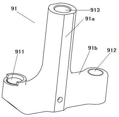
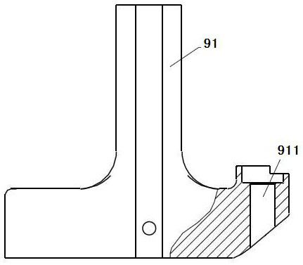
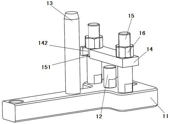
[0020] Figure 3 to Figure 5 The structure of an assembly tool according to an embodiment of the present invention is shown. see Figure 3 to Figure 5 According to an embodiment of the present invention, an assembly tool for a valve bridge assembly includes a base 11, a guide post 13 matching with the middle through hole 913 of the valve bridge 91, and a positioning pin matching with the adjusting screw hole 912 of the valve bridge 91 12. A pressure plate 14, a pair of studs 15 and a pair of nuts 16 for pressing the cross arm portion 91b of the valve bridge during assembly.

[0021] The lower ends of the guide column 13, the lower ends of the positioning pins 12 and the lower ends of a pair of studs 15 are connected to the base 11 respectively. In this embodiment, the lower end of the guide post 13, the lower end of the positioning pin 12 ...


PUM


Abstract

An assembly tool for a valve bridge assembly, comprising a base, a guide column matched with the middle through hole of the valve bridge, a positioning pin matched with the adjustment screw hole of the valve bridge, and a cross arm used to press the valve bridge during assembly The upper part of the pressure plate, a pair of studs and a pair of nuts. The lower end of the guide column, the lower end of the positioning pin and the lower ends of a pair of studs are respectively connected with the base; a pair of studs pass through the pressure plate, and a pair of nuts are respectively screwed with the upper ends of a pair of studs to be pressed and fixed during assembly platen. The invention also discloses an assembly method of the valve bridge assembly. The invention can realize the reliable positioning of the valve bridge, avoid the rotation and inclination of the valve bridge during assembly, make the assembly operation more convenient, and ensure that the valve top cover is assembled in place.

Description

technical field [0001] The invention relates to a maintenance tool for a marine diesel engine. Background technique [0002] The valve bridge assembly is one of the important components of the gas distribution mechanism of a marine diesel engine. It is used to control the opening and closing of the air valve, bear the elastic force of the air valve spring, and receive the reciprocating elastic force when the diesel engine is running, which has a great impact on the working life and reliability of the diesel engine air valve. all have important influences. figure 1 and figure 2 The structure of the valve bridge is shown. The valve bridge assembly mainly consists of valve bridge 91 and valve top cover 92 (see Figure 6 )composition. Wherein, the valve bridge 91 is in an inverted T shape and includes a vertical arm portion 91a and a cross arm portion 91b. The lower end of the vertical arm portion 91a is connected to the cross arm portion 91b. The middle through hole 913 o...

Claims


Application Information

Patent Timeline
Patent Type & Authority Patents(China)
IPC IPC(8): B25B27/24B25B11/00B23P19/027
CPCB23P19/027B25B11/00B25B27/24
Inventor 王维东程世昌徐彦李耀宗林琳徐俊
Owner 中国船舶集团有限公司第七一一研究所
Why Eureka
Try Eureka