A paper tube cutting device

A cutting device and paper tube technology, applied in metal processing and other directions, can solve the problem of manual loading and unloading, and achieve the effect of reducing manual labor, reducing operation difficulty, and reducing equipment cost

Active Publication Date: 2021-08-06
PINGHU DAHONG PAPER TUBE
View PDF0 Cites 1 Cited by
  • Summary
  • Abstract
  • Description
  • Claims
  • Application Information

AI Technical Summary

Problems solved by technology

[0006] In view of the above problems, the present invention provides a paper tube cutting device, which tightens the workpiece and drives the paper tube to rotate through the jacking mechanism. When the first cylinder pushes the cutting assembly forward, the cutter cuts the paper tube. The first cylinder While pushing the cutting component back, it drives the conveyor belt to move forward and transport the next workpiece to the cutting station, which solves the traditional technical problem of manual loading and unloading, realizes automatic continuous cutting, and reduces manual labor

Method used


Image

  • A paper tube cutting device
  • A paper tube cutting device
  • A paper tube cutting device

Examples


Embodiment

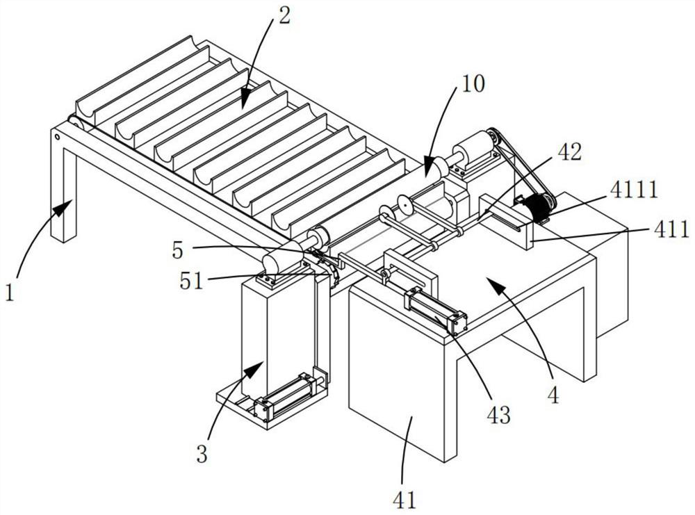
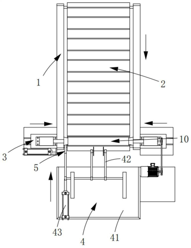
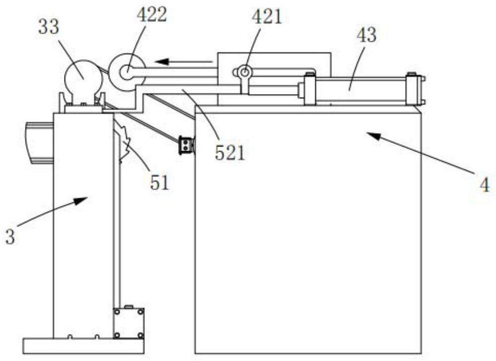
[0049] Such as figure 1 , 2 , 3 and 4, a paper tube cutting device comprising:

[0050] Rack 1;

[0051] Conveying mechanism 2, described conveying mechanism 2 is arranged on described frame 1, and it conveys workpiece 10 along the length direction of described frame 1, and this conveying mechanism 2 comprises first transmission roller 21, second transmission roller 22 and conveyor belt 23. The first transmission roller 21 and the second transmission roller 22 are rotatably arranged on the frame 1, and the conveyor belt 23 is set outside the first transmission roller 21 and the second transmission roller 22;

[0052] The two tightening mechanisms 3 are arranged symmetrically on both sides of the conveying mechanism 2, and they can tighten the two ends of the workpiece 10, and drive the workpiece 10 to rotate. The position of the tightening mechanism 3 corresponding to the conveying mechanism 2 is a cutting station;

[0053] Cutting mechanism 4, described cutting mechanism ...


PUM


Abstract

The invention relates to the technical field of paper tube cutting equipment, in particular to a paper tube cutting device; it includes: a frame; a conveying mechanism, the conveying mechanism includes a first transmission roller, a second transmission roller and a conveyor belt; The position of the mechanism corresponding to the conveying mechanism is the cutting station; the cutting mechanism, the cutting mechanism is located behind the conveying mechanism along the conveying direction of the conveying mechanism; and the linkage mechanism, the linkage mechanism includes a ratchet and a linkage assembly, and the ratchet is arranged on one side of the second transmission roller , when the first cylinder drives the linkage assembly to move backward, the linkage assembly drives the ratchet to rotate; the present invention tightens the workpiece through the jacking mechanism and drives the paper tube to rotate, while the first cylinder pushes the cutting assembly forward, the cutter cuts the paper tube, While the first cylinder pushes the cutting assembly back, it drives the conveyor belt to move forward to transport the next workpiece to the cutting station, realizing automatic continuous cutting and reducing manual labor.

Description

technical field [0001] The invention relates to the technical field of paper tube cutting equipment, in particular to a paper tube cutting device. Background technique [0002] At present, some winding products such as paper rolls, film rolls or film rolls, etc., are soft and easy to tear when the products are unfolded, so these products need to be wound on the rolls to improve the overall rigidity of the products. To ensure normal transportation and storage. [0003] The material of the roll is mostly paper rolls, the main reason is that the paper roll has good mechanical strength, is easy to process, and is more friendly to the environment. Therefore, paper rolls are widely used for winding paper rolls, film rolls, etc. product. [0004] In the field of actual processing and production of paper tubes, a long length of paper tube raw materials is usually produced in advance, and then the paper tube raw materials are cut according to the expected length requirements to obt...

Claims


Application Information

Patent Timeline
Patent Type & Authority Patents(China)
IPC IPC(8): B26D1/15B26D7/26B26D7/02B26D7/06B26D7/32
CPCB26D1/15B26D7/02B26D7/06B26D7/2635B26D7/32
Inventor 赵长春
Owner PINGHU DAHONG PAPER TUBE
Why Eureka
Try Eureka