Pipe laser cutting machine with continuous cutting function

A laser cutting machine, laser cutting technology, applied in laser welding equipment, welding/cutting auxiliary equipment, auxiliary devices, etc., can solve the problems of low cutting efficiency, waste of time, etc., and achieve the effect of improving efficiency and saving manpower

Pending Publication Date: 2019-06-14
安徽同兴科技发展有限责任公司
View PDF0 Cites 2 Cited by
  • Summary
  • Abstract
  • Description
  • Claims
  • Application Information

AI Technical Summary

Problems solved by technology

The existing pipe laser cutting machine can only cut one pipe at a time, and the cutting efficiency is low. When it is necessary to cut a large number of pipes of the same type and size, it is necessary to clamp, cut, and unload again and again. ,waste time

Method used


Image

  • Pipe laser cutting machine with continuous cutting function
  • Pipe laser cutting machine with continuous cutting function
  • Pipe laser cutting machine with continuous cutting function

Examples


Embodiment

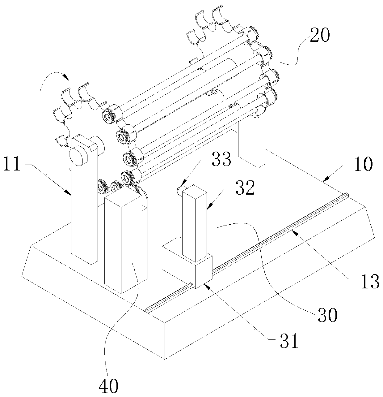
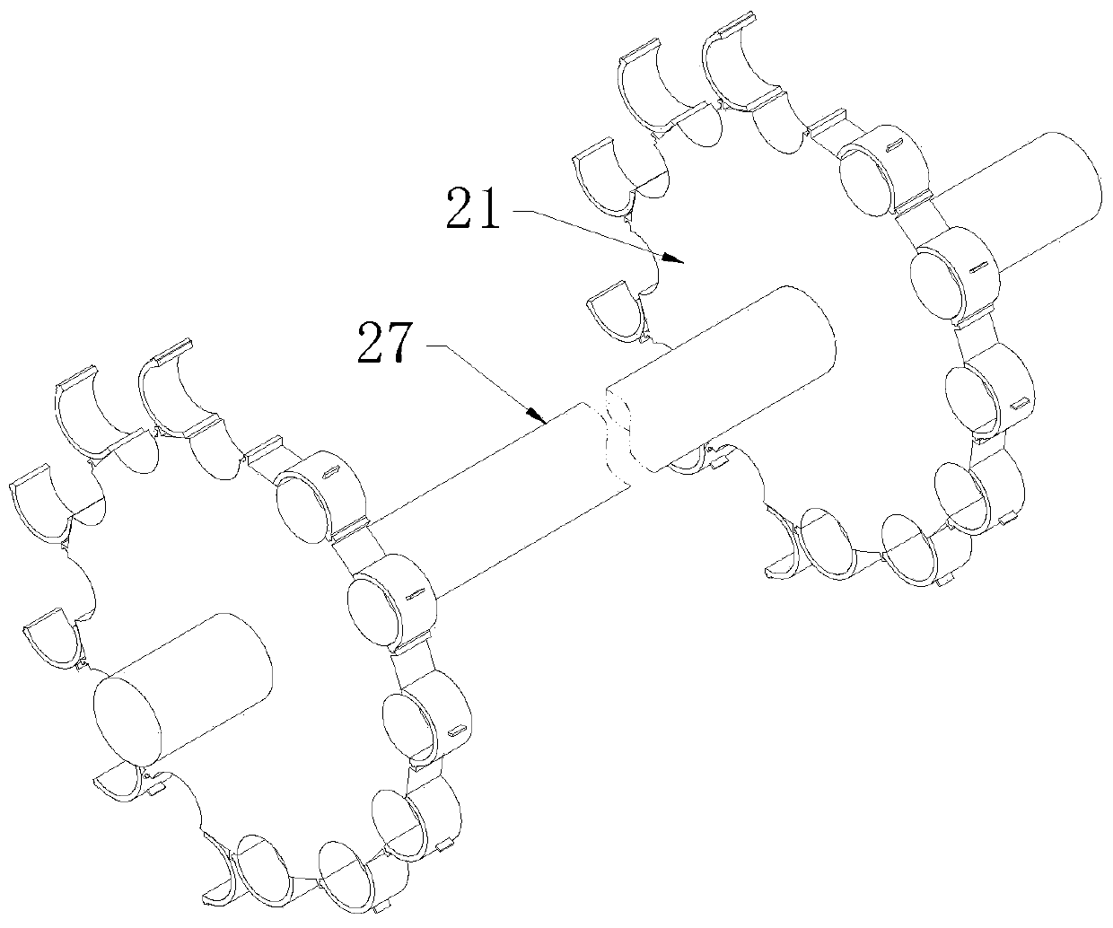
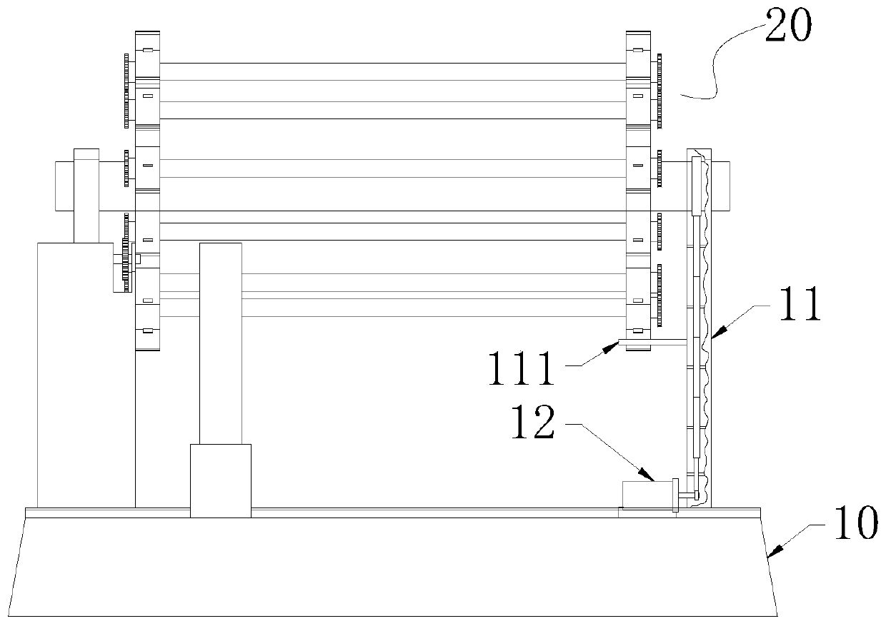
[0026] Such as figure 1 and 2 As shown, a continuous cutting pipe laser cutting machine includes a base 10, a self-rotating pipe fixing device 20 arranged on the top surface of the base 10, a laser cutting device 30 arranged on the side of the pipe fixing device 20, and a set Between the pipe fixing device 20 and the laser cutting device 30, there is a drive system 40 for driving the pipe to rotate. The pipe fixing device 20 includes a shaft 27 that rotates around the central axis and a shaft that is coaxially arranged with the shaft 27 for fixing the pipe. Chucks 21 , the chucks 21 are fixed on the shaft 27 and evenly distributed along the length direction of the shaft 27 .

[0027] The pipe falls on the chuck 21 through the feeding device, and is fixed on the chuck 21 by the fixing device. The shaft 27 is driven to rotate, which drives the pipe on the chuck 21 to rotate. When the pipe moves to the drive system 40, The shaft 27 loses its drive, the chuck 21 stops rotating, ...


PUM


Abstract

The invention discloses a pipe laser cutting machine with a continuous cutting function. The pipe laser cutting machine comprises a base; a rotating pipe fixing device is arranged on top surface of the base; the pipe fixing device comprises a shaft rod rotating around a central axis and chucks coaxially arranged with the shaft rod and used for fixing a pipe, wherein the chucks are fixed on the shaft rod and uniformly distributed along the length direction of the shaft rod; a laser cutting device is arranged on the side of the pipe fixing device; and a driving system is arranged between the pipe fixing device and the laser cutting device and used for driving the pipe to rotate. The rotating pipe fixing device is arranged to fix the pipe and transmit the pipe to the laser cutting device; thedriving system realizes rotating of the pipes during cutting process and automatic continuous cutting of a large number of pipes; a large amount of manpower is saved; and the cutting efficiency is improved.

Description

technical field [0001] The invention belongs to the technical field of laser cutting machines, in particular to a continuous cutting pipe laser cutting machine. Background technique [0002] The laser cutting machine focuses the laser light emitted from the laser device into a high power density laser beam through the optical path system. The laser beam irradiates the surface of the workpiece to make the workpiece reach the melting point or boiling point, and at the same time, the high-pressure gas coaxial with the beam blows away the molten or vaporized metal. With the movement of the relative position of the beam and the workpiece, the material will eventually form a slit, so as to achieve the purpose of cutting. [0003] When the laser cutting machine is used to cut pipes, it is usually necessary to set the pipe to move or the laser head to move constantly to complete the cutting of the pipe. The existing pipe laser cutting machine can only cut one pipe at a time, and t...

Claims


Application Information

Patent Timeline
Patent Type & Authority Applications(China)
IPC IPC(8): B23K26/70B23K37/047B23K26/38
Inventor 罗群罗亮
Owner 安徽同兴科技发展有限责任公司
Why Eureka
Try Eureka