Correction device for evaporation and correction method

A technology of vapor deposition and locking devices, which is applied in the field of correction devices for vapor deposition, can solve the problems of inconsistency in the uniformity of the inner and outer sides of the laser, and achieve the effect of improving the yield and satisfying the consistency

Active Publication Date: 2019-12-10
潍坊华光光电子有限公司
View PDF6 Cites 3 Cited by
  • Summary
  • Abstract
  • Description
  • Claims
  • Application Information

AI Technical Summary

Problems solved by technology

[0004] In the prior art, although there is a mechanism for adding a correction plate during coating to improve the evaporation effect, the existing correction plate generally adopts an offset and fixed structure, which still cannot make the inner and outer sides of the laser on the carrier stand well during coating. The uniformity problem

Method used


Image

  • Correction device for evaporation and correction method
  • Correction device for evaporation and correction method

Examples


Embodiment 1

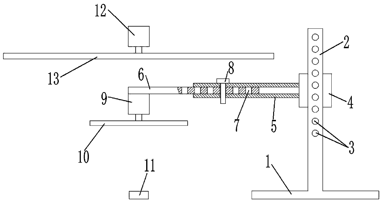
[0033] The locking device I includes a number of sockets I3 arranged at intervals along the axial direction of the column 2 and a positioning hole I arranged on the sleeve 4 to match the socket I3. When an socket I3 is coaxial with the positioning hole I, it can be used The pin shaft I is inserted into the socket I 3 and the positioning hole I. By adjusting the height of the casing 4, when the appropriate height is reached and the jack I 3 coincides coaxially with the positioning hole I, the pin shaft I can be inserted to lock, and the operation is simple.

Embodiment 2

[0035] The above-mentioned locking device II includes a plurality of jacks II 7 arranged at intervals along the axial direction of the cross-branch 6 and a positioning hole II arranged on the cross-branch 5 to match the jacks II 7. When a jack II 7 is the same as the positioning hole II Insert the pin shaft II 8 into the socket II 7 and the positioning hole II behind the shaft. Adjust the position of the horizontal strut 6 horizontally. After the adjustment is in place and the coaxial coincidence of the jack II 7 and the positioning hole II, insert the pin II 8 to lock, and the operation is simple.

Embodiment 3

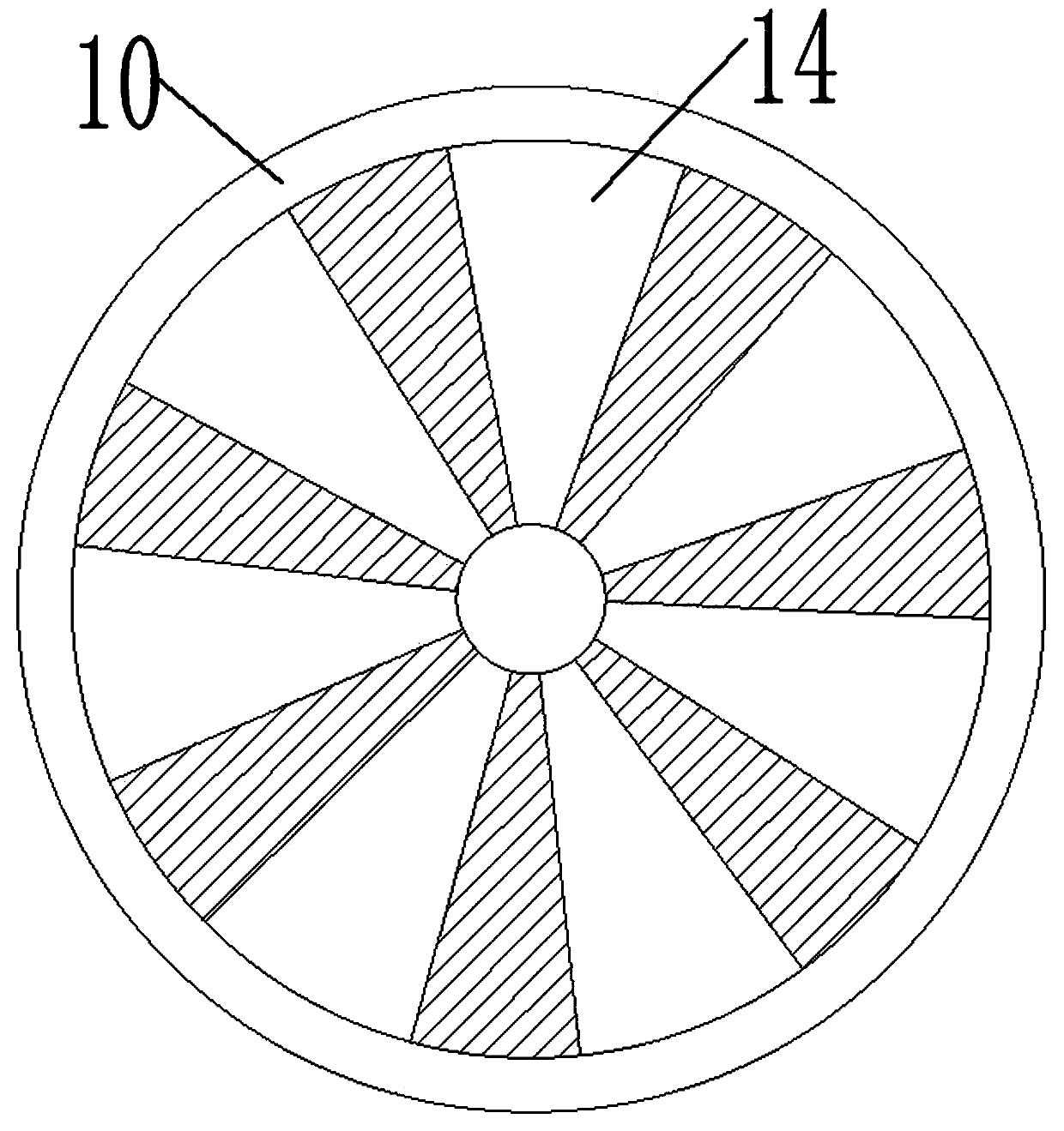
[0037] Preferably, N is a positive integer greater than or equal to 3, and 3 or more correction holes 14 can better guide the evaporated material, further improving the uniformity of evaporation.


PUM


Abstract

The invention provides a correction device for evaporation and a correction method. A transverse supporting rod is moved transversely to ensure that a baffle plate is coaxial with a bearing frame anda crucible; after the transverse supporting rod is moved in place, the transverse supporting rod is locked by a locking device II. The height of a casing pipe can be adjusted along a stand column by moving the casing pipe, and thus, the relative height of the baffle plate relative to the bearing frame can be adjusted; and after the casing pipe is adjusted in place, the casing pipe is locked by a locking device I. A plurality of correction holes are formed in the baffle plate in the circumferential direction and are of sector structures, the positions, close to the center of a circle, of the correction holes have small openings, and the outer sides of the correction holes have big openings, so that when an evaporation material heated in the crucible evaporates, the flow quantity and flow rate of the evaporation material after the evaporation material passes the correction holes at the positions close to the center of the circle are smaller than the flow quantity and flow rate of the evaporation material passing the outer sides of the correction holes, thus, when a motor II drives the bearing frame to rotate, a laser on the bearing frame can achieve the effect of uniform evaporationinside and outside, the evaporation quality can be consistent, and the rate of finished products is increased.

Description

technical field [0001] The invention relates to the technical field of semiconductor laser packaging, in particular to a correction device and a correction method for vapor deposition. Background technique [0002] During the packaging process of semiconductor lasers, the laser needs to be coated to improve the light output efficiency and protect the laser. The evaporation chamber of the existing electron beam evaporation technology generally includes an evaporation source, which is installed above the evaporation source to carry the plated parts. Carrier. Controlling the consistency of products is a key issue in the mass production process, but in practice, products with different evaporation positions in the same heat show different evaporation quality problems, which greatly reduces product consistency and affects product quality. [0003] In order to solve the above problems, analysis of the reasons found that during the evaporation process, the carrier above the center...

Claims


Application Information

Patent Timeline
Patent Type & Authority Applications(China)
IPC IPC(8): C23C14/28C23C14/54
CPCC23C14/28C23C14/547
Inventor 周莉汤庆敏刘存志郑兆河
Owner 潍坊华光光电子有限公司
Why Eureka
Try Eureka