Electrically driven multistage centrifugal compressor device with cooling circulation function

A centrifugal compressor and cooling cycle technology, applied in the field of compressors, can solve problems such as unsatisfactory cooling effect, inability to adjust, and insufficient sealing of connection positions, so as to improve convenience and stability, ensure service life, and ensure flow area Effect

Pending Publication Date: 2019-12-10
MILITARY TRANSPORTATION UNIV PLA
View PDF6 Cites 0 Cited by
  • Summary
  • Abstract
  • Description
  • Claims
  • Application Information

AI Technical Summary

Problems solved by technology

[0003] When the compressor is in use, because the air is compressed at a high speed, a large amount of heat will be generated, but the cooling effect of the existing compressor is not ideal, and it is easy to cause damage to the internal blades and affect the service life; moreover, most of the existing compressors are used Installed on a fixedly connected base, the height cannot be adjusted according to the needs of on-site installation, and the installation work is not smooth; in addition, the outlet pipe is a fixed-length structure. When connecting with gas equipment, it is easy to be unable to adjust because the installation position is fixed. , can not adapt to the distance between the two devices, it is easy to cause insufficient sealing of the connection position, and affect the stability of the gas pressure

Method used


Image

  • Electrically driven multistage centrifugal compressor device with cooling circulation function
  • Electrically driven multistage centrifugal compressor device with cooling circulation function
  • Electrically driven multistage centrifugal compressor device with cooling circulation function

Examples


Embodiment Construction

[0020] The following will clearly and completely describe the technical solutions in the embodiments of the present invention with reference to the accompanying drawings in the embodiments of the present invention. Obviously, the described embodiments are only some, not all, embodiments of the present invention. Based on the embodiments of the present invention, all other embodiments obtained by persons of ordinary skill in the art without making creative efforts belong to the protection scope of the present invention.

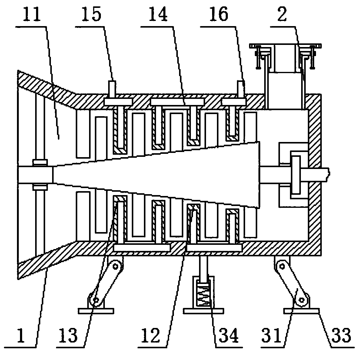
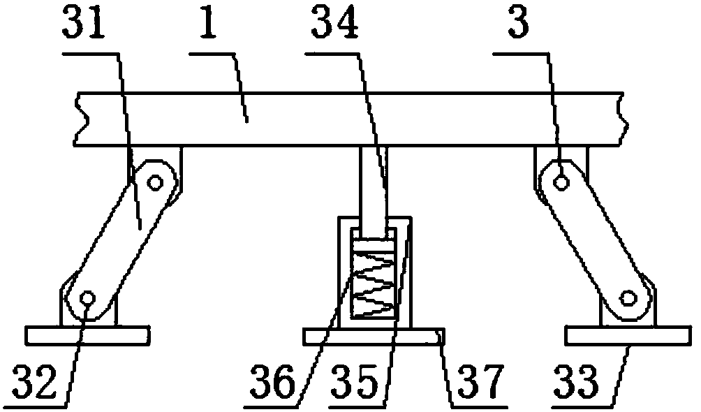
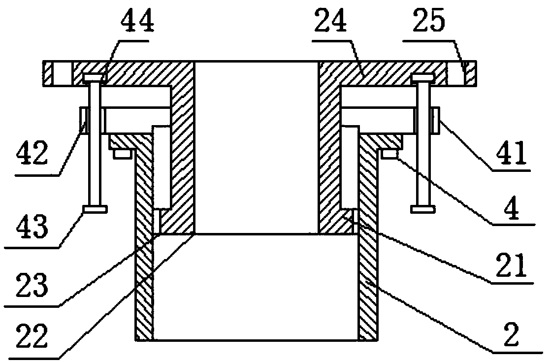
[0021] see Figure 1-3 , the present invention provides a technical solution: a novel electric-driven multi-stage centrifugal compressor device with cooling cycle function, comprising a shell 1, the front surface of the shell 1 is provided with an air inlet 11, the inner side of the shell 1 The surface is fixedly connected with the stator blade 12, and the interior of the stator blade 12 is provided with a cooling chamber 13. The stator blade 12 and the coolin...


PUM


Abstract

Provided is an electrically driven multistage centrifugal compressor device with a cooling circulation function. An air inlet is formed in the surface of the front end of a shell, a stator blade is fixedly connected to the surface of the inner side of the shell, a cooling cavity is formed in the stator blade, the outer surface of the cooling cavity is fixedly connected to the inside of the shell through a circulation cavity, and a water inlet pipe and a water outlet pipe are arranged at the two ends of the outer surface of the circulation cavity respectively; the two sides of the lower surfaceof the shell are hinged with swing supporting rods through first hinge shafts, and the bottoms of the swing supporting rods are hinged with first mounting plates through second hinge shafts; the rearside of the upper surface of the shell is provided with an air outlet pipe, the inside of the air outlet pipe is slidably connected with an extension pipe through a connection plate, the front end ofthe air outlet pipe is fixedly connected with a pressing plate, the inside of the pressing plate is slidably connected with the front end of the outer surface of the extension pipe, and the two endsof the outer side of the front end face of the pressing plate are connected with threaded rods. The device has the advantages that the installation height can be adjusted, the tension degree is guaranteed, the convenience and stability of use are improved and the service life is prolonged.

Description

technical field [0001] The invention relates to the technical field of compressors, in particular to an electrically driven multistage centrifugal compressor device with a cooling cycle function. Background technique [0002] The air enters the compressor from the air inlet, and enters the impeller through the guidance of the wind guide wheel that rotates together with the impeller. Under the action of the high-speed rotating impeller, the air is thrown from the center of the impeller to the outer edge of the impeller by centrifugal force, and the pressure gradually increases. After the air flowing out of the impeller enters the diffuser, the speed decreases, the pressure increases again, and finally flows out of the compressor through the outlet pipe. [0003] When the compressor is in use, because the air is compressed at a high speed, a large amount of heat will be generated, but the cooling effect of the existing compressor is not ideal, and it is easy to cause damage to...

Claims


Application Information

Patent Timeline
Patent Type & Authority Applications(China)
IPC IPC(8): F04D29/58F04D29/44F04D29/42F04D29/62F04D17/12F04D25/08
CPCF04D29/5846F04D29/441F04D29/4206F04D29/624F04D17/12F04D25/08F04D29/584F04D17/122F04D29/5826F04D29/542F04D29/601F05D2230/642
Inventor 刘瑞林夏南龙
Owner MILITARY TRANSPORTATION UNIV PLA
Why Eureka
Try Eureka