
System and method for measuring deflection angle error of laser radar

A deflection angle error, laser radar technology, applied in radio wave measurement systems, measurement devices, optical devices, etc., can solve the problems of laser beam damage, measurement device damage, and low measurement results Simple and easy to achieve effect

Active Publication Date: 2019-12-10
SUZHOU HUAXING YUANCHUANG TECH CO LTD
View PDF6 Cites 12 Cited by
  • Summary
  • Abstract
  • Description
  • Claims
  • Application Information

AI Technical Summary

Problems solved by technology

However, the laser band is invisible, and the laser beam has the ability to damage under high power, which leads to the damage of the measuring device when directly using the measuring device to measure the lidar, which in turn affects the performance of the measuring device, making the accuracy of the measurement result not high.

Method used


Image

  • System and method for measuring deflection angle error of laser radar
  • System and method for measuring deflection angle error of laser radar
  • System and method for measuring deflection angle error of laser radar

Examples


Embodiment Construction

[0030] In order to further explain the technical means and effects of the present invention to achieve the intended purpose of the invention, the specific implementation of a laser radar deflection angle error measurement system and method according to the present invention will be implemented below in conjunction with the accompanying drawings and preferred embodiments Mode, structure, feature and effect thereof are as follows in detail.

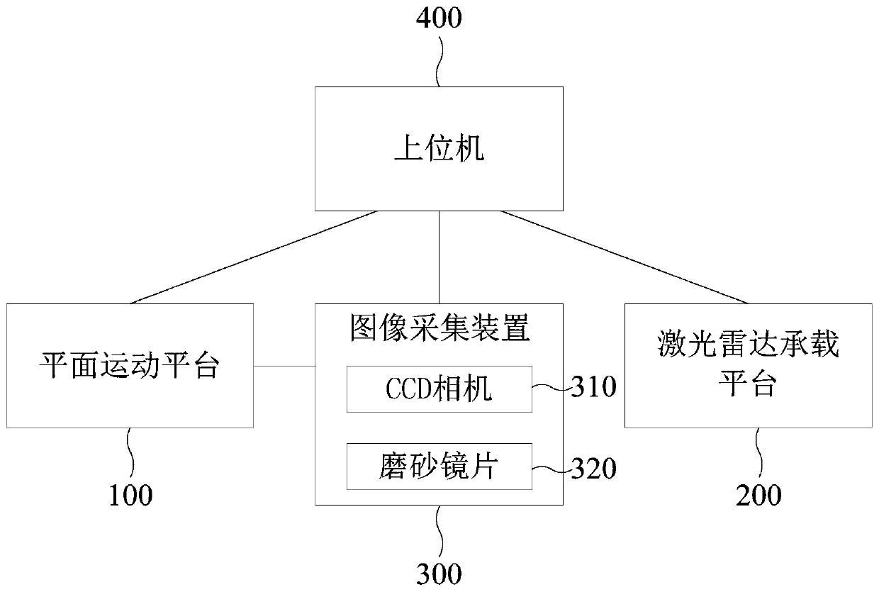
[0031] An embodiment of the present invention provides a laser radar deflection angle error measurement system, including:

[0032] Planar motion platform, laser radar carrying platform, image acquisition device and host computer;

[0033] Wherein, the image acquisition device is connected to the planar motion platform, and the planar motion platform is used to drive the image acquisition device to move on the trajectory plane;

[0034] The laser radar carrying platform is used to carry the laser radar to be tested, and calibrate the posit...


PUM


Abstract

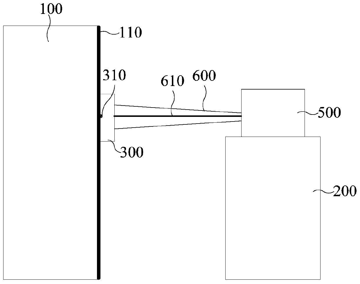
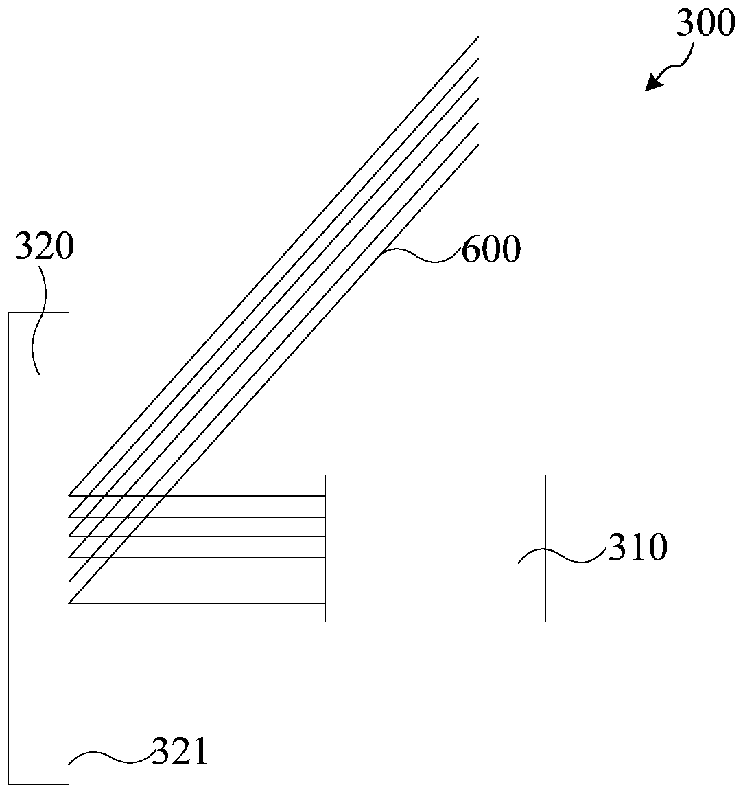
The invention discloses a system and method for measuring a deflection angle error of a laser radar. The system comprises a planar motion platform, a laser radar bearing platform, an image acquisitiondevice and an upper computer, wherein the planar motion platform is used for driving the image acquisition device to move on a track plane; the laser radar bearing platform is used for bearing a laser radar to be measured and calibrating the position of the laser radar to be measured; the image acquisition device comprises a CCD camera and a frosted lens; a laser beam emitted by the laser radar to be measured forms a light spot on the first surface of the frosted lens, and the CCD camera is used for acquiring an image of the light spot; and the upper computer is connected with the planar motion platform, the laser radar bearing platform and the image acquisition device. According to the technical scheme provided by the embodiment of the invention, a phenomenon that damage is caused by direct incidence of a high-energy laser beam into a measuring device is avoided, the improvement of the precision of a measurement result is facilitated, and the measurement process of the deflection angle error is simple and easy to realize.

Description

technical field [0001] Embodiments of the present invention relate to the technical field of laser radar parameter measurement, and in particular to a system and method for measuring a laser radar deflection angle error. Background technique [0002] With the continuous development of laser technology, lidar is widely used in various fields of social life, especially in the field of autonomous driving, where its advantages of accuracy and efficiency are prominent. [0003] The data accuracy of the lidar is closely related to the safety of the vehicle, so it is necessary to measure the deflection angle error of the lidar. However, the laser band is invisible, and the laser beam has the ability to damage under high power. As a result, the measurement device is easily damaged when the measurement device is directly used to measure the lidar, which in turn affects the performance of the measurement device, making the accuracy of the measurement results not high. Contents of th...

Claims


Application Information

Patent Timeline
IPC IPC(8): G01B11/26G01S7/481G01S7/497
CPCG01B11/26G01S7/481G01S7/497
Inventor 刘成宇周俊
Owner SUZHOU HUAXING YUANCHUANG TECH CO LTD
Learn More