MIMO annular array azimuth imaging method and device for microwave frequency band

A ring array and imaging method technology, which is applied in the field of MIMO array imaging signal processing, can solve problems such as the inability to achieve target omni-directional imaging, and the large blind area of ​​the planar MIMO array.

Active Publication Date: 2019-12-10
INST OF ELECTRONICS CHINESE ACAD OF SCI
View PDF12 Cites 4 Cited by
  • Summary
  • Abstract
  • Description
  • Claims
  • Application Information

AI Technical Summary

Problems solved by technology

However, there is a large blind area in the planar MIMO array, which cannot realize omni-directional imaging of the target.

Method used


Image

  • MIMO annular array azimuth imaging method and device for microwave frequency band
  • MIMO annular array azimuth imaging method and device for microwave frequency band
  • MIMO annular array azimuth imaging method and device for microwave frequency band

Examples


Embodiment Construction

[0021] In order to make the object, technical solution and advantages of the present invention clearer, the present invention will be further described in detail below in conjunction with specific embodiments and with reference to the accompanying drawings.

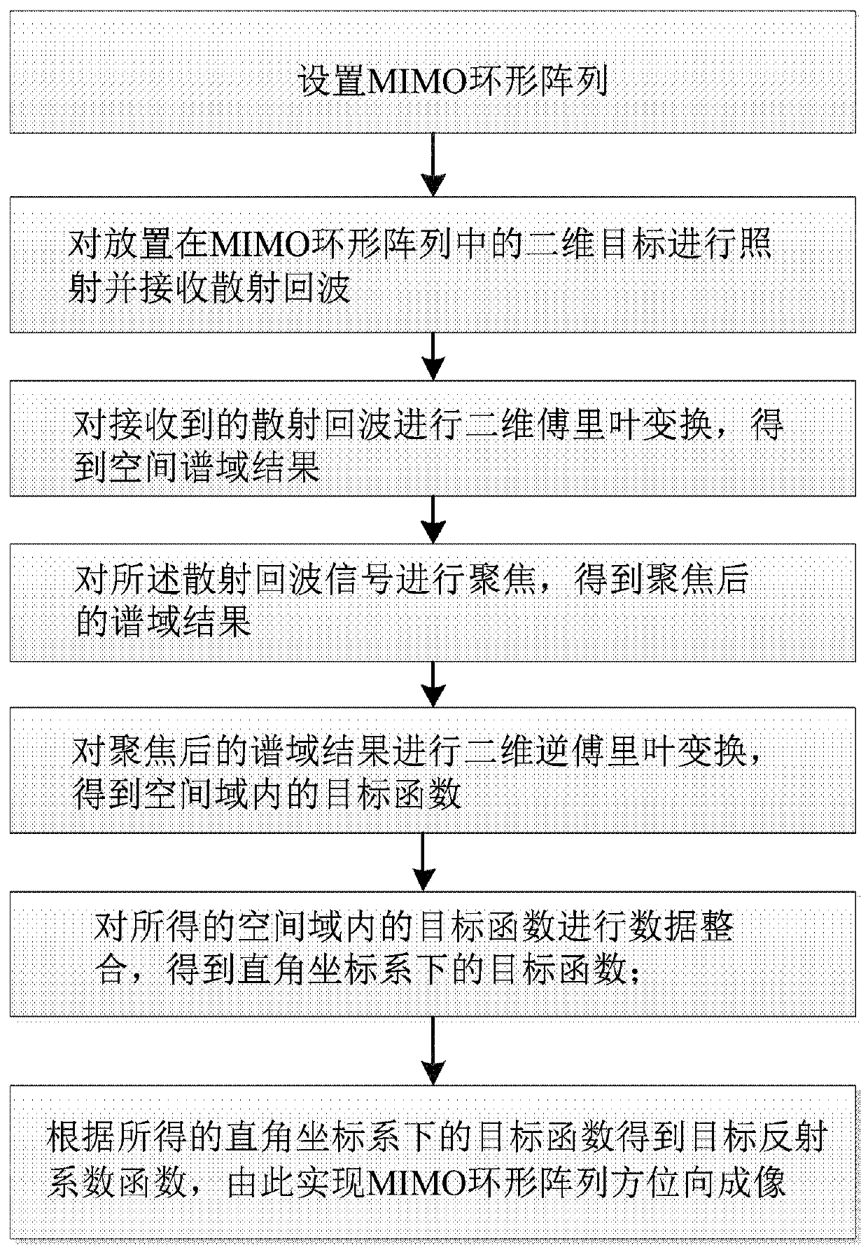
[0022] The invention discloses a MIMO ring array azimuth imaging method, comprising the following steps:

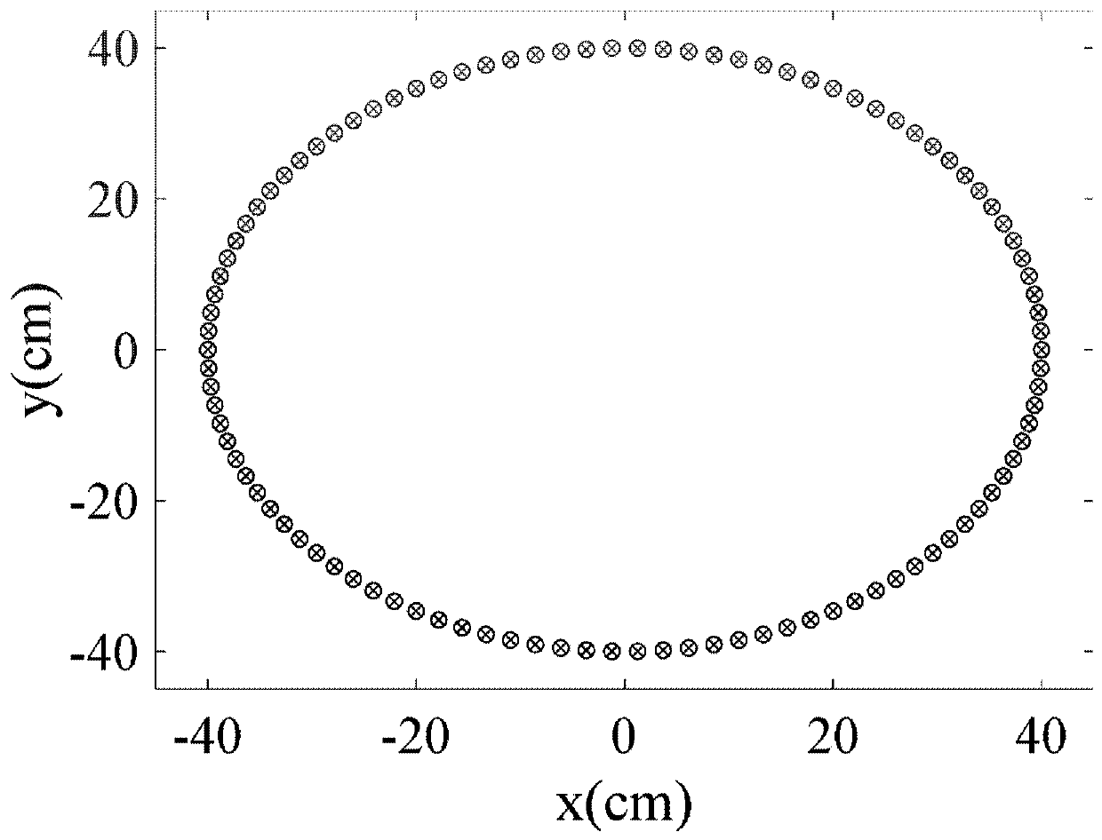
[0023] A. Set the MIMO ring array;

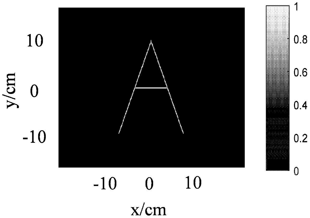
[0024] B. Illuminate the two-dimensional target placed in the MIMO ring array and receive the scattered echo;

[0025] C. Perform two-dimensional Fourier transform on the received scattered echo to obtain the spatial spectral domain result;

[0026] D. Focusing the scattered echo signal to obtain a focused spectral domain result;

[0027] E. Perform a two-dimensional inverse Fourier transform on the focused spectral domain results to obtain the objective function in the spatial domain;

[0028] F, carry out data integration to the objective function in the obtained space domain...


PUM


Abstract

The invention discloses an MIMO annular array azimuth imaging method and device for a microwave frequency band. The method comprises the following steps: setting an MIMO annular array; irradiating thetwo-dimensional target placed in the MIMO annular array and receiving scattered echoes; performing two-dimensional Fourier transform on the received scattered echoes to obtain a spatial spectral domain result; focusing the scattered echo signal to obtain a focused spectral domain result; performing two-dimensional inverse Fourier transform on the focused spectral domain result to obtain an objective function in a spatial domain; performing data integration on the obtained target function in the spatial domain to obtain a target function under a rectangular coordinate system; and obtaining a target reflection coefficient function according to the obtained target function under the rectangular coordinate system, thereby realizing MIMO annular array azimuth imaging. By means of the rapid imaging method based on the array, high-quality and high-efficiency azimuth imaging of the target can be achieved.

Description

technical field [0001] The invention relates to the technical field of MIMO array imaging signal processing, in particular to a method and device for azimuth imaging of a MIMO ring array in a microwave frequency band. Background technique [0002] In the application of MIMO (Multiple Input Multiple Output) array imaging, the MIMO array structure and high-efficiency imaging method are the focus of imaging technology. For traditional MIMO arrays, such as linear MIMO arrays and planar rectangular MIMO arrays, many fast imaging methods have been developed. However, there is a large blind area in the planar MIMO array, which cannot realize omni-directional imaging of the target. Therefore, the present invention designs a ring-shaped MIMO array, which can realize omni-directional observation and imaging of the target without contacting the target. Based on the ring MIMO array, a fast and efficient azimuth imaging method is developed, which can quickly reconstruct the target imag...

Claims


Application Information

Patent Timeline
Patent Type & Authority Applications(China)
IPC IPC(8): G01S13/89G01S7/285G01S7/35G01S7/41
CPCG01S7/285G01S7/352G01S7/41G01S13/89
Inventor 吴世有王慧黄玲方广有
Owner INST OF ELECTRONICS CHINESE ACAD OF SCI
Why Eureka
Try Eureka