
Novel synchronous reluctance rotor structure

A technology of synchronous reluctance and rotor structure, which is applied to synchronous motors, electrical components, and electromechanical devices for single-phase currents. Effect of torque ripple and reduction of radial centrifugal force

Pending Publication Date: 2019-12-10
深圳市百晟传动有限公司
View PDF0 Cites 0 Cited by
  • Summary
  • Abstract
  • Description
  • Claims
  • Application Information

AI Technical Summary

Problems solved by technology

[0003] The main purpose of the present invention is to propose a new type of synchronous reluctance rotor structure, which aims to solve the technical problems mentioned in the background technology, realize the self-starting function, and make up for the defect of the existing synchronous reluctance motor with large torque ripple

Method used


Image

  • Novel synchronous reluctance rotor structure
  • Novel synchronous reluctance rotor structure
  • Novel synchronous reluctance rotor structure

Examples


Embodiment Construction

[0015] It should be understood that the specific embodiments described here are only used to explain the present invention, not to limit the present invention. It should be noted that relative terms such as "first", "second" and so on may be used to describe various components, but these terms do not limit the components. These terms are only used to distinguish one component from another. For example, without departing from the scope of the present invention, a first component may be called a second component, and a second component may similarly be called a first component. The term "and / or" refers to any one or more combination of related items and described items.

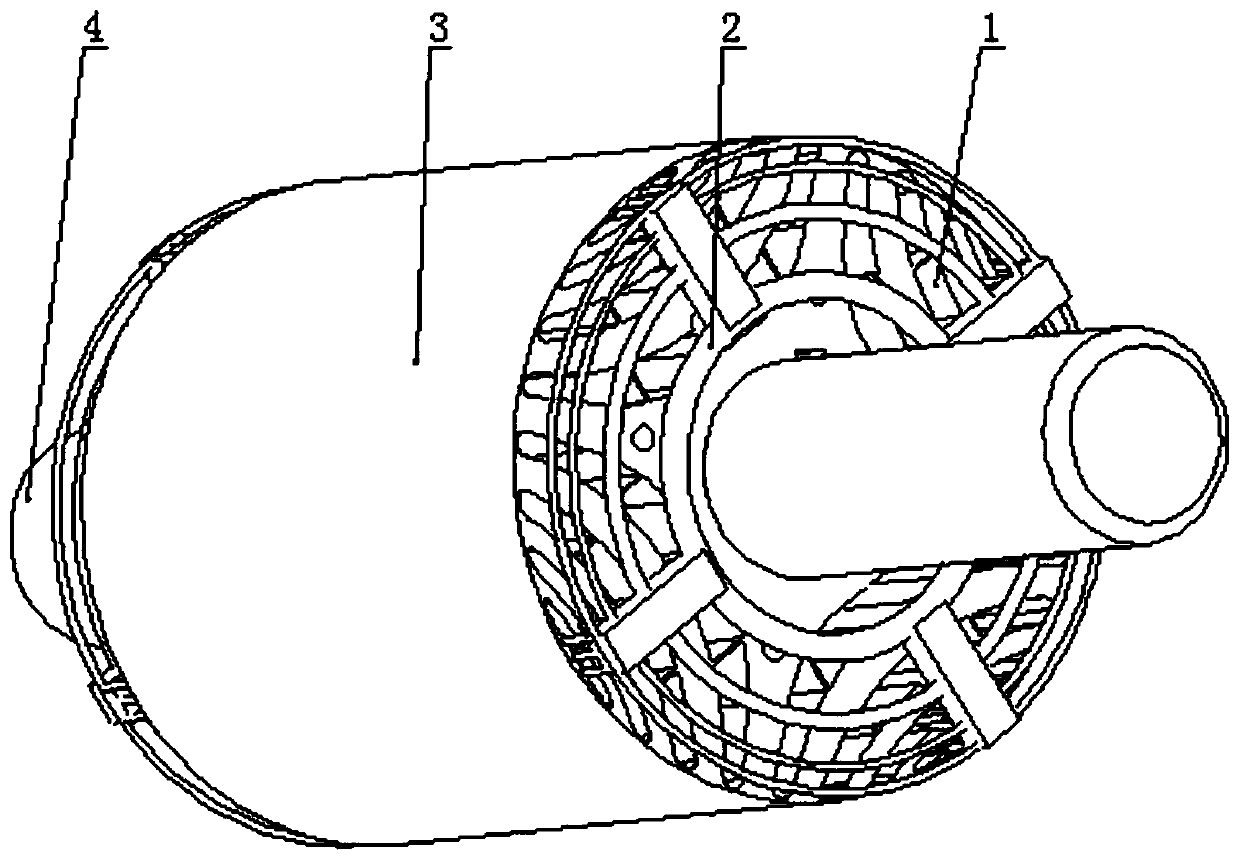
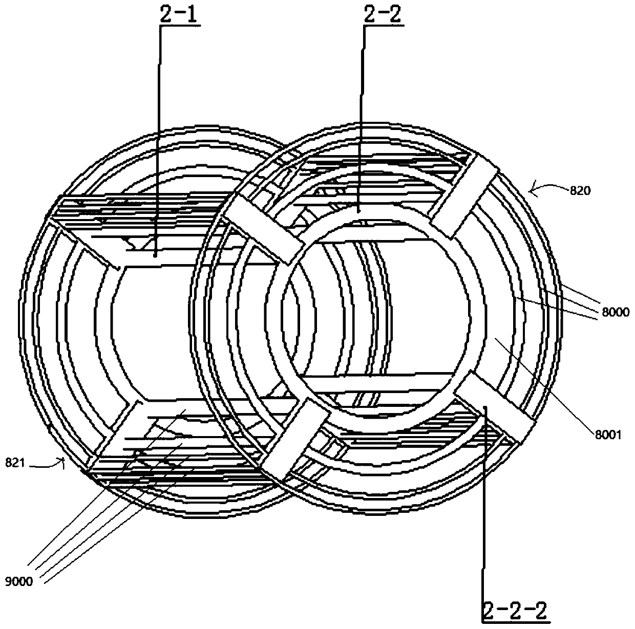
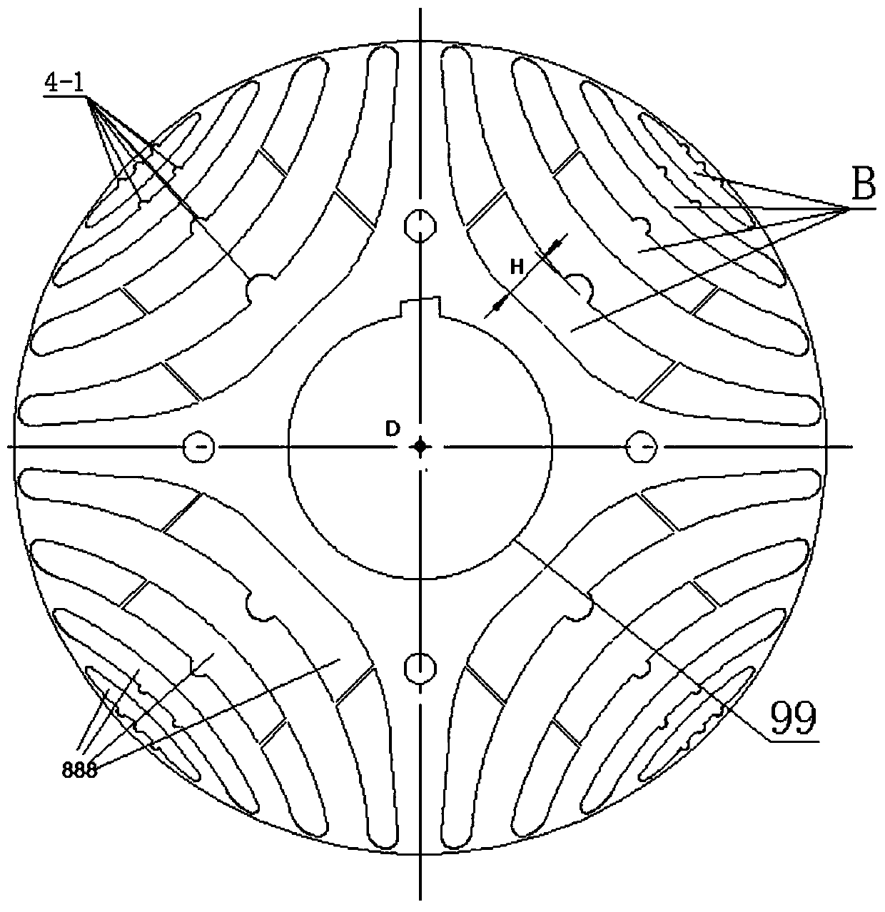
[0016] like figure 1 , figure 2 , image 3 as shown, figure 1 It is the first three-dimensional schematic diagram of the novel synchronous reluctance rotor structure of the present invention; figure 2 It is a structural schematic diagram of the cage bar assembly in the novel synchronous reluctance rotor...


PUM


Abstract

The invention discloses a novel synchronous reluctance rotor structure, which comprises a rotor core provided with a rotating shaft hole and a cage bar assembly, wherein the cage bar assembly comprises a first linear copper bar, a first copper circular ring and a second copper circular ring, the rotating shaft hole is internally provided with a rotating shaft, one end of the first linear copper bar penetrates through a magnetic grid group on the rotor core and then is connected with the first circular ring on one side of the rotor core, and the other end of the first linear copper bar is connected with the second circular ring on the other side of the rotor core. The novel synchronous reluctance rotor structure is particularly suitable for a synchronous reluctance motor, can realize a self-starting function, and can make up the defect of large torque ripple of the existing synchronous reluctance motor.

Description

technical field [0001] The invention belongs to the technical field of synchronous reluctance motor structure, and in particular relates to a novel synchronous reluctance rotor structure. Background technique [0002] At present, the synchronous reluctance motor has the advantages of light weight and wide speed regulation range, but there are also defects such as poor mechanical strength of the rotor and large pulsating torque. Compared with the induction motor, since it cannot be started directly, an external controller is required, which not only increases the cost, reduces the overall reliability of the motor, but also brings difficulties to the controller. Contents of the invention [0003] The main purpose of the present invention is to propose a new synchronous reluctance rotor structure, which aims to solve the technical problems mentioned in the background art, realize the self-starting function, and make up for the defect of large torque ripple of the existing syn...

Claims


Application Information

Patent Timeline
IPC IPC(8): H02K19/14H02K29/03
CPCH02K19/14H02K29/03
Inventor 张波张晓晨
Owner 深圳市百晟传动有限公司
Learn More