Method for operating a drive control device, facility with means for executing the method and drive control device with such a facility

a technology of drive control and control device, which is applied in the direction of control system, power conversion system, electrical apparatus, etc., can solve the problems of negative regulation effect, lower utilization of converter, and inability to achieve optimal, so as to improve torque quality and increase converter utilization

Active Publication Date: 2016-11-29
SIEMENS AG
View PDF33 Cites 0 Cited by
  • Summary
  • Abstract
  • Description
  • Claims
  • Application Information

AI Technical Summary

Benefits of technology

[0009]The effect of the rotation of the current vector (iαβ) initially present in the first coordinate system by the transformation angle (φfSH) into the second coordinate system is that in the resulting current vector (ixy) in the second coordinate system—more precisely in the time curve of the resulting current vector (ixy(t))—the subharmonics occurring become zero-frequency quantities. Such zero-frequency quantities can be easily be regulated out with a regulator.
[0027]The approach presented here enables subharmonics in the output voltages (motor voltages) and currents to be avoided for ripple DC link circuit voltages at critical output frequencies, especially in the overload range. In these ranges this allows an improvement in the torque quality and also in the converter loading and allows a greater converter utilization. Thus the demand for an output voltage corresponding to the input voltage with diode supply in the critical frequency ranges without destructive subharmonics is also able to be realized.

Problems solved by technology

This is the case for example during an overload or during a non-ideal compensation by temporal delay of the voltage measurement.
In this case the voltage harmonics generate high harmonic content in the output currents which have a negative effect on the regulation, the quality of the torque and the load on the inverter.
This leads however to a lower utilization of the converter, since in these ranges the maximum output voltage is no longer available.
In addition it is not optimal with previous approaches that with a non-ideal compensation of the DC link circuit voltage, subharmonic content which has to be taken into account still remains in the linear range of the modulator.

Method used


Image

  • Method for operating a drive control device, facility with means for executing the method and drive control device with such a facility
  • Method for operating a drive control device, facility with means for executing the method and drive control device with such a facility
  • Method for operating a drive control device, facility with means for executing the method and drive control device with such a facility

Examples


Embodiment Construction

[0035]Throughout all the figures, same or corresponding elements may generally be indicated by same reference numerals. These depicted embodiments are to be understood as illustrative of the invention and not as limiting in any way. It should also be understood that the figures are not necessarily to scale and that the embodiments are sometimes illustrated by graphic symbols, phantom lines, diagrammatic representations and fragmentary views. In certain instances, details which are not necessary for an understanding of the present invention or which render other details difficult to perceive may have been omitted.

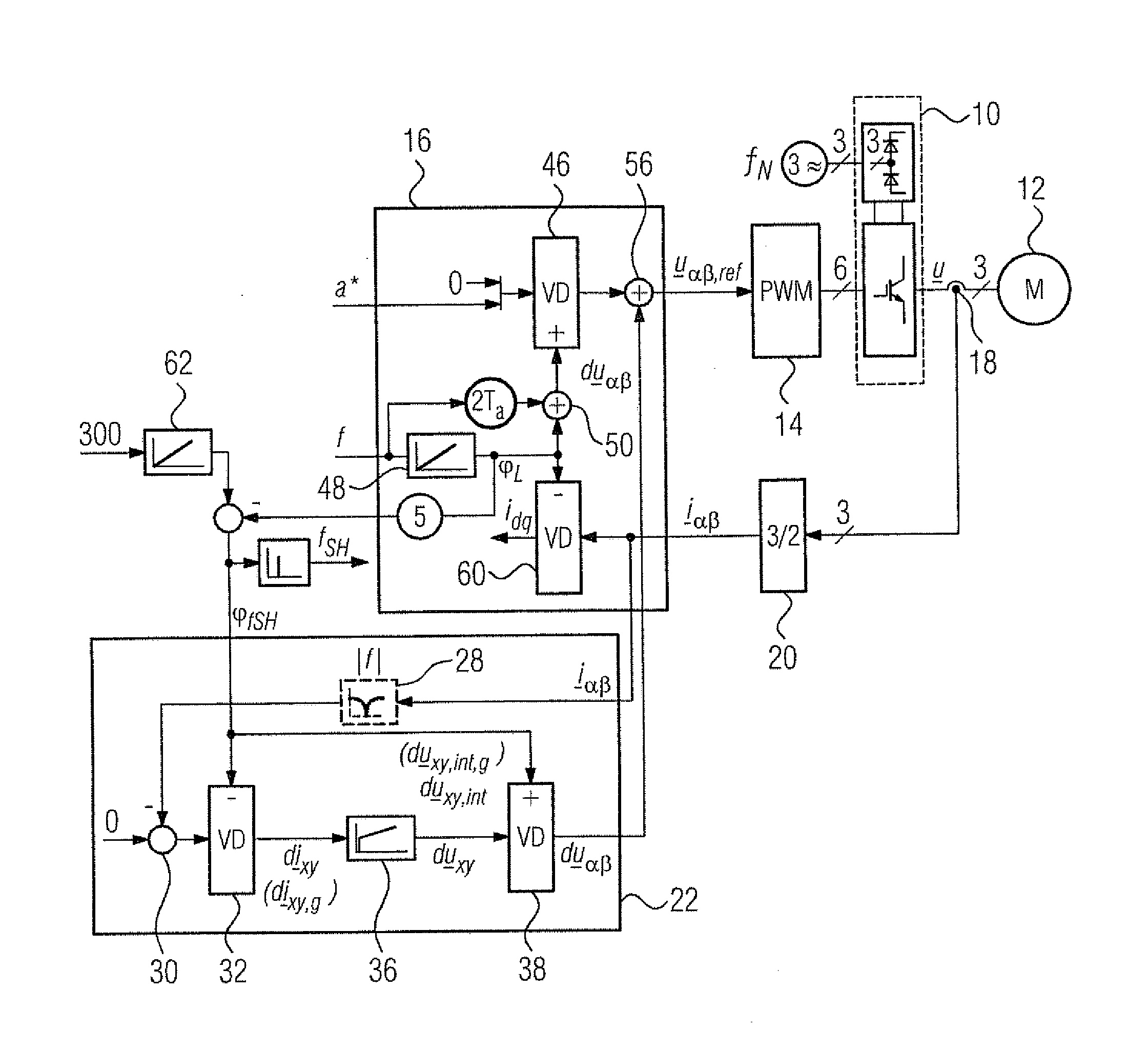
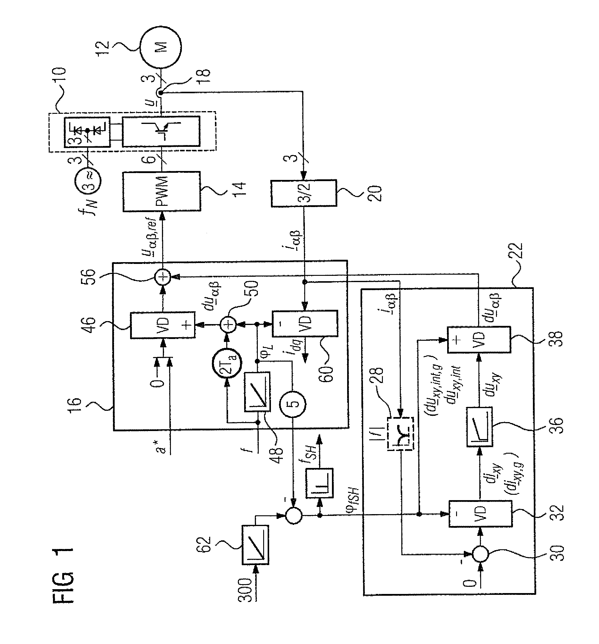
[0036]Turning now to the drawing, and in particular to FIG. 1, there is shown for the case of U / f control, a block diagram of an embodiment for regulating out subharmonics with the critical harmonic orders mentioned above. The principle underlying the block diagram can of course also be used for other harmonic orders (v=−7, 11, 13, . . . ).

[0037]On the far right the block di...


PUM


Abstract

A drive controller and a method for operating a drive controller having a converter with a DC link circuit, includes measuring during operation phase currents generated by the converter; forming from the measured phase currents a current vector in a first coordinate system; rotating, with a first transformation angle and with a first rate of change, the current vector into a second coordinate system to generate a resulting current vector; supplying the resulting current vector to a regulator to generate a resulting voltage vector at an output of the regulator; rotating, with the first transformation angle or with a second transformation angle rotating at the first rate of change, the resulting voltage vector back into the first coordinate system to generate a resulting back-transformed voltage vector; and using the resulting back-transformed voltage vector as an influencing variable in addition to U / f control or vector regulation for controlling the converter.

Description

CROSS-REFERENCES TO RELATED APPLICATIONS[0001]This application claims the priority of European Patent Application, Serial No. 13172257.1, filed Jun. 17, 2013, pursuant to 35 U.S.C. 119(a)-(d), the content of which is incorporated herein by reference in its entirety as if fully set forth herein.BACKGROUND OF THE INVENTION[0002]The present invention relates to a method for operating a drive control device, a facility with means for executing the method and a drive control device with such a facility.[0003]The following discussion of related art is provided to assist the reader in understanding the advantages of the invention, and is not to be construed as an admission that this related art is prior art to this invention.[0004]In many applications, for a converter drive with a DC link circuit, referred to here and below in general terms as a drive control device, because of so-called harmonics a DC link ripple voltage arises. If for example the DC link circuit is fed from an uncontroll...

Claims


Application Information

Patent Timeline
Patent Type & Authority Patents(United States)
IPC IPC(8): H02M1/12H02M7/5387H02P29/00
CPCH02M7/53875H02P21/22H02P29/50H02M2007/53876H02M7/53876
Inventor BAUER, FRANZSCHIERLING, HUBERT
Owner SIEMENS AG
Why Eureka
Try Eureka