
Low-noise, high rotor pole switched reluctance motor

a high-rotor pole and resistance motor technology, applied in the direction of electrical apparatus, dynamo-electric machines, control systems, etc., can solve the problems of unreliable position estimation, no electromagnetic relation that can be used to predict different configurations, etc., to improve the torque quality of the machine, reduce noise and vibration, and increase the inductance rate

Active Publication Date: 2022-03-08
TURNTIDE TECH INC
View PDF14 Cites 0 Cited by
  • Summary
  • Abstract
  • Description
  • Claims
  • Application Information

AI Technical Summary

Benefits of technology

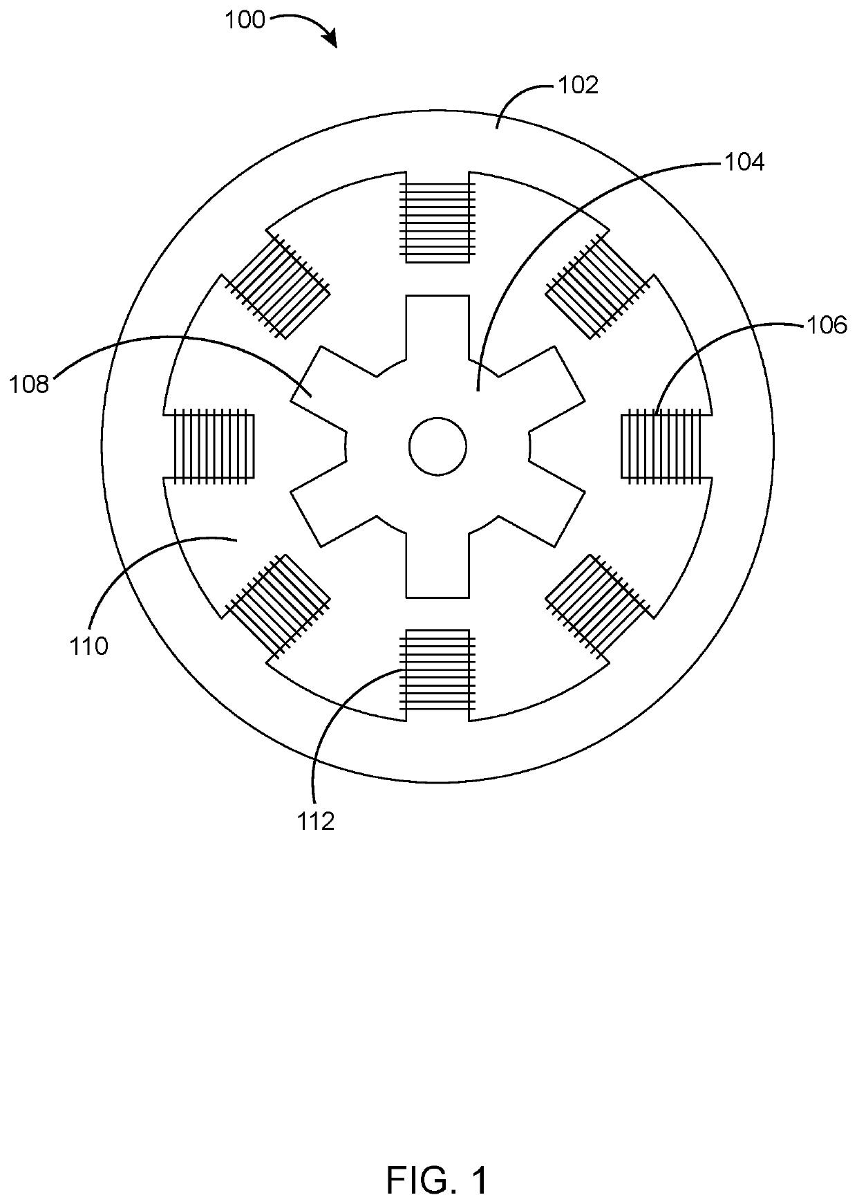
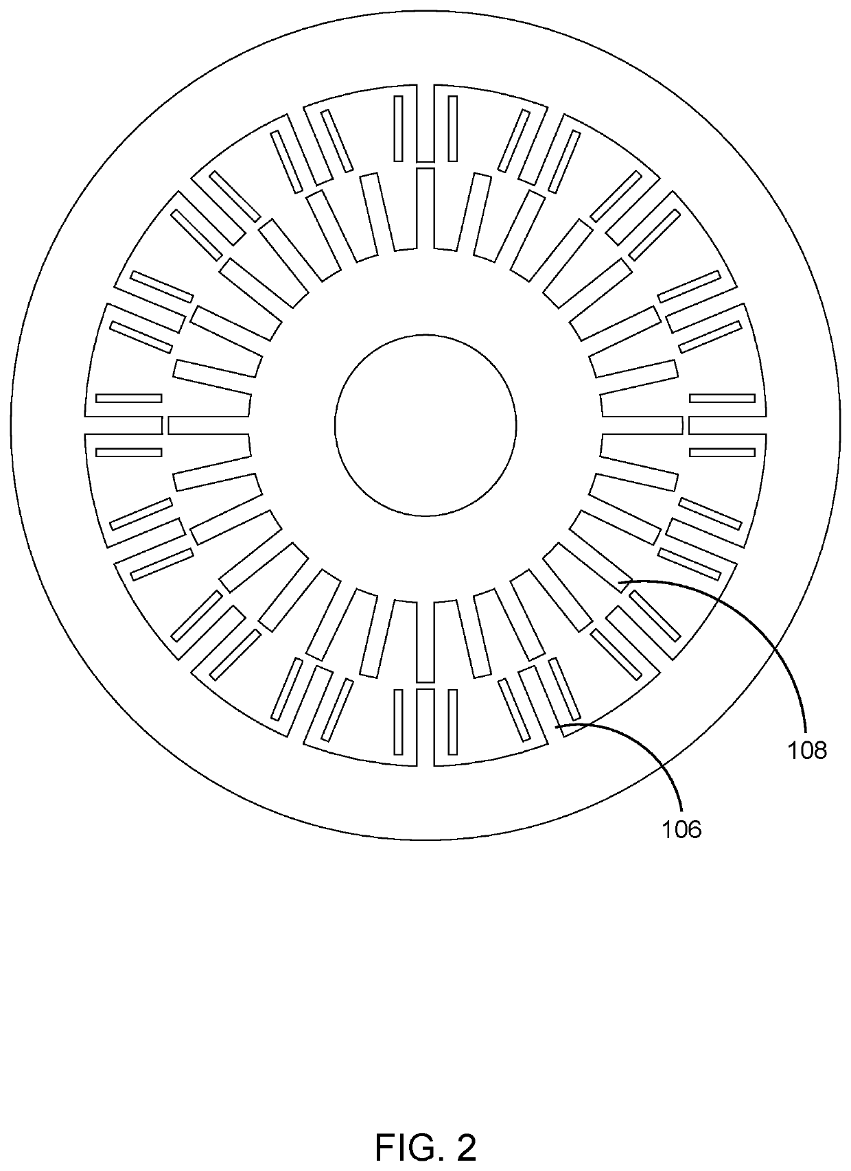
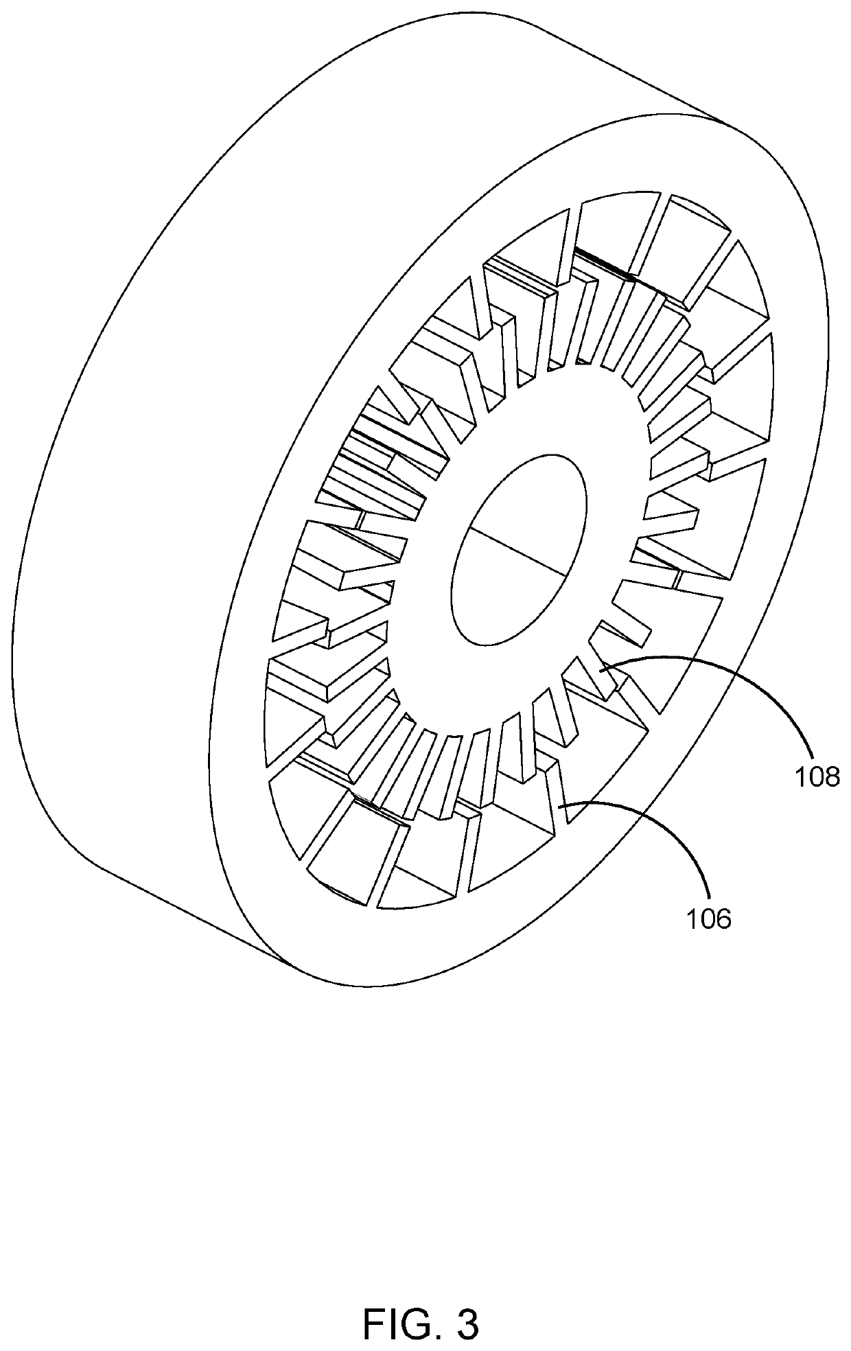
[0010]The present invention relates to a switched reluctance machine (SRM) in which noise and vibration generated can be reduced through an improvement of the rotor pole / stator pole configuration. The improved configuration provides a higher rate of change of inductance with respect to rotor position, which can improve the torque quality of the machine. The proposed formulation presents a mathematical formulation, with a specific number of stator and rotor poles for a chosen m and Fp, which provides improved noise performance and design flexibility. In one example, when m=4, a machine with four phases and Fp=4, which represents a machine with four possible independent flux paths, resulting in a 16 / 28 SRM. The embodiment of this formulation may be described by several other viable combinations of stator poles and rotor poles. Utilizing the proposed formulation, it is possible to design machines with varying number of phases and stator / rotor configurations. The present invention provides an SRM with applications for both rotary or linear designs, and which comprises a relationship between the number of stator poles and rotor poles so as to provide an SRM with a minimal amount of torque ripple and acoustic noise while providing improved power density and torque production. In particular, the present invention provides an SRM having a salient rotor and stator pole numerical relationship of Sn number of stator poles, and Rn number of rotor poles, which can be expressed as Rn=2Sn−Fp, such as a machine with a Sn / Rn pole count in a 16 / 28 configuration. The present invention provides an SRM, whether operated as a motor, generator, or both. The proposed topologies have the highest inductance when aligned and the lowest at unaligned positions, much like a conventional SRM. All conventional power electronic converters and control strategies adopted for conventional SRMs may be applied to the proposed SRM. The proposed SRM exhibits a smoother torque profile due to the higher number of strokes per revolution. This offers better peak and average torque profiles relative to conventional SRMs.
[0011]A first objective of the present invention is to provide an HRSRM with reduced noise properties and vibration levels generated from the machine during operation.
[0012]A second objective of the present invention is to provide an HRSRM with minimal amount of torque ripple and enhanced torque quality of the machine as compared to conventional SRMs and HRSRMs.
[0013]A third objective of the present invention is to provide an HRSRM with high power density and torque.
[0016]A sixth objective of the present invention is to provide an HRSRM exhibiting high reliability and efficiency, thereby reducing the consumer cost of such motors.

Problems solved by technology

As a result, the self-inductance profile for the HRSRM becomes flatter which leads to unreliable position estimation.
This conventional approach introduces one more geometric shape for the HRSRM with reduced stator, however, it does not show any electromagnetic relation that can be used to predict different configurations.

Method used


Image

  • Low-noise, high rotor pole switched reluctance motor
  • Low-noise, high rotor pole switched reluctance motor
  • Low-noise, high rotor pole switched reluctance motor

Examples


Embodiment Construction

[0029]In the following discussion that addresses a number of embodiments and applications of the present invention, reference is made to the accompanying drawings that form a part hereof, and in which is shown by way of illustrating specific embodiments in which the invention may be practiced. It is to be understood that other embodiments may be utilized and changes may be made without departing from the scope of the present invention.

[0030]Various inventive features are described below that can each be used independently of one another or in combination with other features. However, any single inventive feature may not address any of the problems discussed above or only address one or more of the problems discussed above. Further, one or more of the problems discussed above may not be fully addressed by any of the features described below. The invention will now be described with reference to the accompanying drawing which does not limit the scope and the ambit of the invention. In...


PUM


Abstract

The present embodiment is a high rotor pole switched reluctance machine (HRSRM) which provides a plurality of combinations of the number of rotor poles Rn and number of stator poles Sn utilizing a numerical relationship defined by a mathematical formula, Rn=2Sn−Fp, when Sn=m×Fp, wherein Fp is the maximum number of independent flux paths in the stator when stator and rotor poles are fully aligned, and m is the number of phases. The mathematical formulation provides an improved noise performance and design flexibility to the machine. The mathematical formulation further provides a specific number of stator and rotor poles for a chosen m and Fp. The HRSRM can be designed with varying number of phases. The HRSRM provides a smoother torque profile due to a high number of strokes per revolution.

Description

RELATED APPLICATIONS[0001]This application is a continuation application based on U.S. patent application Ser. No. 16 / 461,483, filed May 16, 2019 and granted as U.S. Pat. No. 10,707,798 on Jul. 7, 2020, and which is a 35 U.S.C. 371 national phase application claiming priority to the International Application PCT / US2017 / 068829, filed Dec. 28, 2017.BACKGROUND OF THE DISCLOSURETechnical Field of the Disclosure[0002]The present disclosure relates in general to high rotor pole switched reluctance machines (HRSRM), and more particularly to a system and method for providing a plurality of combinations of rotor poles and stator poles thereby reducing noise and vibration in the switched reluctance motor drives.Description of the Related Art[0003]Recent advances in electromagnetic simulation capabilities and power electronics have made switched reluctance motor (SRM) an attractive candidate for electric motor applications. Positive aspects of SRM drives include their inherent variable speed c...

Claims


Application Information

Patent Timeline
Patent Type & Authority Patents(United States)
IPC IPC(8): H02P25/098H02K37/04
CPCH02P25/098H02K37/04H02K2213/03H02K19/103
Inventor KRISHNAMURTHY, MAHESHCREARY, TREVORDESAI, PIYUSHJOHNSTON, MARK
Owner TURNTIDE TECH INC
Learn More