
Demonstrator capable of delaying 30 seconds

A demonstrator and time technology, applied in the field of automatic control delay circuit, can solve problems such as lack of instruments, and achieve the effect of strong brightness, stable working performance and simple working circuit

Inactive Publication Date: 2019-12-10
雷建设
View PDF0 Cites 0 Cited by
  • Summary
  • Abstract
  • Description
  • Claims
  • Application Information

AI Technical Summary

Problems solved by technology

[0002] The delay function of the delayer is commonly used in the design of electronic circuits. It can play a role in the stability and reliability of the designed circuit. At present, there is a lack of instruments in this area in the teaching of general technical courses in ordinary middle schools and in the practical activities of electronic technology. Therefore, Invent a demonstrator with a time delay of 30 seconds

Method used


Image

  • Demonstrator capable of delaying 30 seconds

Examples


Embodiment Construction

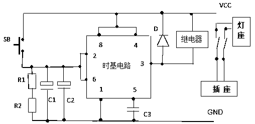
[0009] See figure 1 As shown, a demonstrator with a time delay of 30 seconds includes a time base circuit, a relay, a resistor, a capacitor, a diode, a button, a socket and a lamp holder, and the resistor includes a resistor R1, a resistor R2, and a capacitor Including capacitor C1, capacitor C2, and capacitor C3, the button is SB, the negative pole of the circuit is GND, and the positive pole of the circuit is VCC. One end of the button SB is connected to the positive pole VCC, and the other end is connected to the time base circuit, relay, and positive pole VCC in sequence. The time base circuit is an integrated block of NE555. After the resistors R1 and R2 are connected in series, one end is connected to pins 2 and 6 of the time base circuit together with the positive poles of the capacitors C1 and C2, and the other end is connected to the negative poles of the capacitors C1 and C2 together. The ground is connected to GND, pin 4 and pin 8 of the time base circuit NE555 are ...


PUM

PropertyMeasurementUnit
Capacitoraaaaaaaaaa

Abstract

The invention particularly relates to a demonstrator capable of delaying 30 seconds. The demonstrator comprises a time-base circuit, a relay, a resistor, a capacitor, a diode, a key, a socket and a lamp holder, the resistors comprise a resistor R1 and a resistor R2; the capacitor comprises a capacitor C1, a capacitor C2 and a capacitor C3; a key SB, the negative electrode of the circuit is groundGND; the positive electrode of the circuit is VCC, one end of the key SB is connected with a positive electrode VCC; the other end is connected with the time-base circuit, the relay and the positive electrode VCC in sequence; the time base circuit is an NE555 integrated block; after resistors R1 and R2 are connected in series, one end of each resistor R1 and R2 is connected with pins 2 and 6 of the time-base circuit together with anodes of a capacitor C1 and a capacitor C2, the other end of each resistor R1 and R2 and cathodes of the capacitor C1 and the capacitor C2 are connected with the ground GND together, and pins 4 and 8 of the time-base circuit NE555 are connected with a circuit VCC. The demonstration instrument is simple in circuit, low in cost, stable in working performance, convenient to operate and use, high in demonstration light brightness, visual and good in teaching effect, and has certain use market and popularization value.

Description

technical field [0001] The patent of the present invention relates to an automatic control delay circuit in the electronic field, in particular to a demonstrator with a delay time of 30 seconds. Background technique [0002] The delay function of the delayer is commonly used in the design of electronic circuits. It can play a role in the stability and reliability of the designed circuit. At present, there is a lack of instruments in this area in the teaching of general technical courses in ordinary middle schools and in the practical activities of electronic technology. Therefore, Invent a demonstrator with a time delay of 30 seconds. Contents of the invention [0003] The patent of the present invention relates to a 30-second delay demonstrator, including a time base circuit, a relay, a resistor, a capacitor, a diode, a button, a socket and a lamp holder, and the resistor includes a resistor R1, a resistor R2, The capacitor includes capacitor C1, capacitor C2, and capaci...

Claims


Application Information

Patent Timeline
IPC IPC(8): H03K17/28
CPCH03K17/28
Inventor 雷建设
Owner 雷建设
Learn More