Apparatus for handling a carrier in a vacuum chamber, vacuum deposition system, and method of handling a carrier in a vacuum chamber

A technology of vacuum chamber and carrier, used in vacuum evaporation coating, semiconductor/solid-state device manufacturing, coating, etc.

Inactive Publication Date: 2019-12-10
APPLIED MATERIALS INC
View PDF5 Cites 2 Cited by
  • Summary
  • Abstract
  • Description
  • Claims
  • Application Information

AI Technical Summary

Problems solved by technology

In particular, it is challenging to accurately and smoothly transport a substrate carrier carrying a substrate and / or a mask carrier carrying a mask through a vacuum system

Method used


Image

  • Apparatus for handling a carrier in a vacuum chamber, vacuum deposition system, and method of handling a carrier in a vacuum chamber
  • Apparatus for handling a carrier in a vacuum chamber, vacuum deposition system, and method of handling a carrier in a vacuum chamber
  • Apparatus for handling a carrier in a vacuum chamber, vacuum deposition system, and method of handling a carrier in a vacuum chamber

Examples


Embodiment Construction

[0022] Reference will now be made in detail to various embodiments of the present disclosure, one or more examples of which are illustrated in the Figures. In the following description of the figures, the same reference numerals refer to the same components. Generally, only differences with respect to a single implementation are described. Each example is provided by way of explanation of the disclosure, and not meant to be a limitation of the disclosure.

[0023] Additionally, features illustrated or described as part of one embodiment can be used on or in conjunction with other embodiments to yield a further embodiment. The intended description includes such modifications and variations.

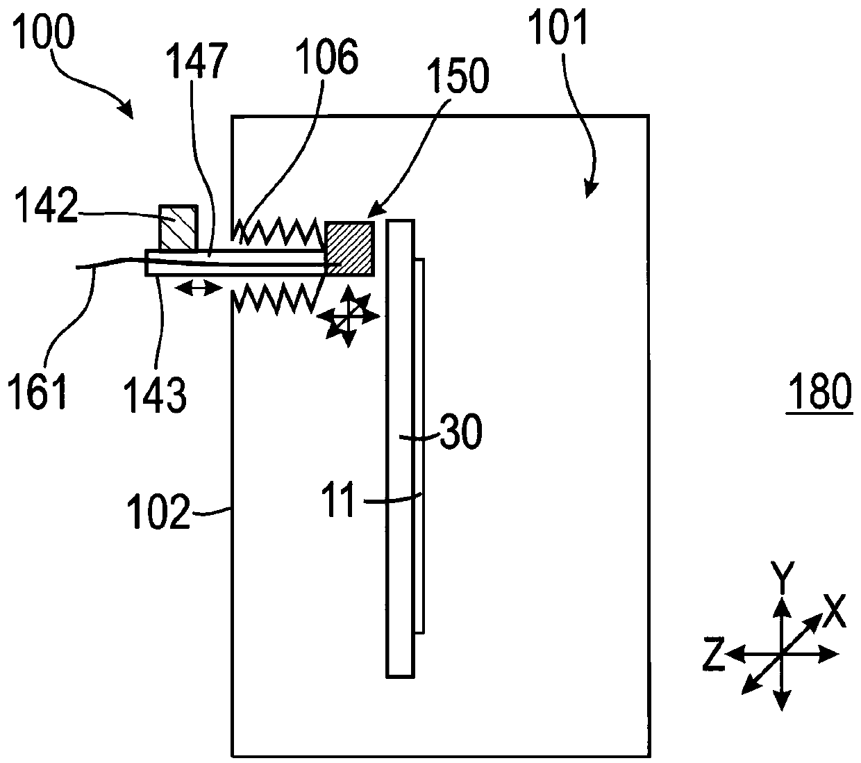
[0024] figure 1 is a schematic cross-sectional view of an apparatus 100 for processing carriers in a vacuum chamber 101 according to embodiments described herein.

[0025] According to this disclosure, "handling a carrier" may, for example, include operations such as moving a carrier, ...


PUM

PropertyMeasurementUnit
surface areaaaaaaaaaaa
thicknessaaaaaaaaaa
thicknessaaaaaaaaaa

Abstract

An apparatus (100) for handling a carrier in a vacuum chamber is described. The apparatus (100) includes a vacuum chamber (101) having a wall (102) with an opening (106). A first driving unit (142) isarranged outside the vacuum chamber (101) and configured to move a first driven part (143) extending through the opening (106) into the vacuum chamber (101). A first component (150) for holding or moving a carrier (30) is attached to the first driven part (143) in the vacuum chamber (101). The first driven part (143) provides a first supply passage (147) for supplying the first component (150). Further, a vacuum deposition system and a method of handling a carrier are described.

Description

technical field [0001] Embodiments of the present disclosure relate to an apparatus for processing a carrier in a vacuum chamber, a vacuum deposition system, and a method of processing a carrier in the vacuum chamber. In particular, embodiments of the present disclosure relate to holding or moving carriers in a vacuum chamber. More specifically, embodiments of the present disclosure relate to holding and moving a carrier in an alignment direction in a vacuum chamber. [0002] Embodiments of the present disclosure are particularly directed to vacuum deposition systems for depositing material on a substrate carried by a carrier, where the substrate is aligned relative to a mask prior to deposition. The methods and apparatus described herein can be used in the fabrication of organic light emitting diode (OLED) devices. Background technique [0003] For example, techniques for layer deposition on substrates include thermal evaporation, physical vapor deposition (PVD) and chemi...

Claims


Application Information

Patent Timeline
Patent Type & Authority Applications(China)
IPC IPC(8): C23C14/04C23C14/50C23C14/56H01L21/67H01L21/68
CPCC23C14/042C23C14/50C23C14/566H01L21/67709H01L21/67712H01L21/682H01L21/67017H01L21/6719H01L21/67196H01L21/6773H01L21/68H01L21/687
Inventor 马蒂亚斯·赫曼尼斯詹斯·格伦斯
Owner APPLIED MATERIALS INC
Why Eureka
Try Eureka