
Automatic spraying system with correcting function for workpiece processing

An automatic spraying and functional technology, applied in spray booths, spraying devices, etc., can solve problems such as occupation of operator time, low efficiency, and easy deviation of workpieces from conveyor belts, and achieve the effect of facilitating accurate spraying, reducing working time, and ensuring spraying quality.

Inactive Publication Date: 2019-12-13
扬州健松涂装材料有限公司
View PDF0 Cites 9 Cited by
  • Summary
  • Abstract
  • Description
  • Claims
  • Application Information

AI Technical Summary

Problems solved by technology

[0003] In order to realize the automation of the spraying system, the existing automatic spraying machines use the conveyor belt to transfer the workpieces, and rely on the operator to place the workpieces on the conveyor belt for transmission, and then transfer the workpieces to the spray booth for spraying operations, but manual placement is used. The method of workpiece is not only inefficient, but also requires the operator to place the workpiece continuously for a long time, which takes up a lot of time for the operator. Moreover, when placing the workpiece, due to the irregular placement position, the workpiece is easy to deviate from the conveyor belt, which not only affects the spraying quality In severe cases, the workpiece will fall from the conveyor belt, causing damage to the workpiece, which in turn reduces the practicability of the existing automatic spraying system

Method used


Image

  • Automatic spraying system with correcting function for workpiece processing
  • Automatic spraying system with correcting function for workpiece processing
  • Automatic spraying system with correcting function for workpiece processing

Examples


Embodiment Construction

[0024] The present invention is described in further detail now in conjunction with accompanying drawing. These drawings are all simplified schematic diagrams, which only illustrate the basic structure of the present invention in a schematic manner, so they only show the configurations related to the present invention.

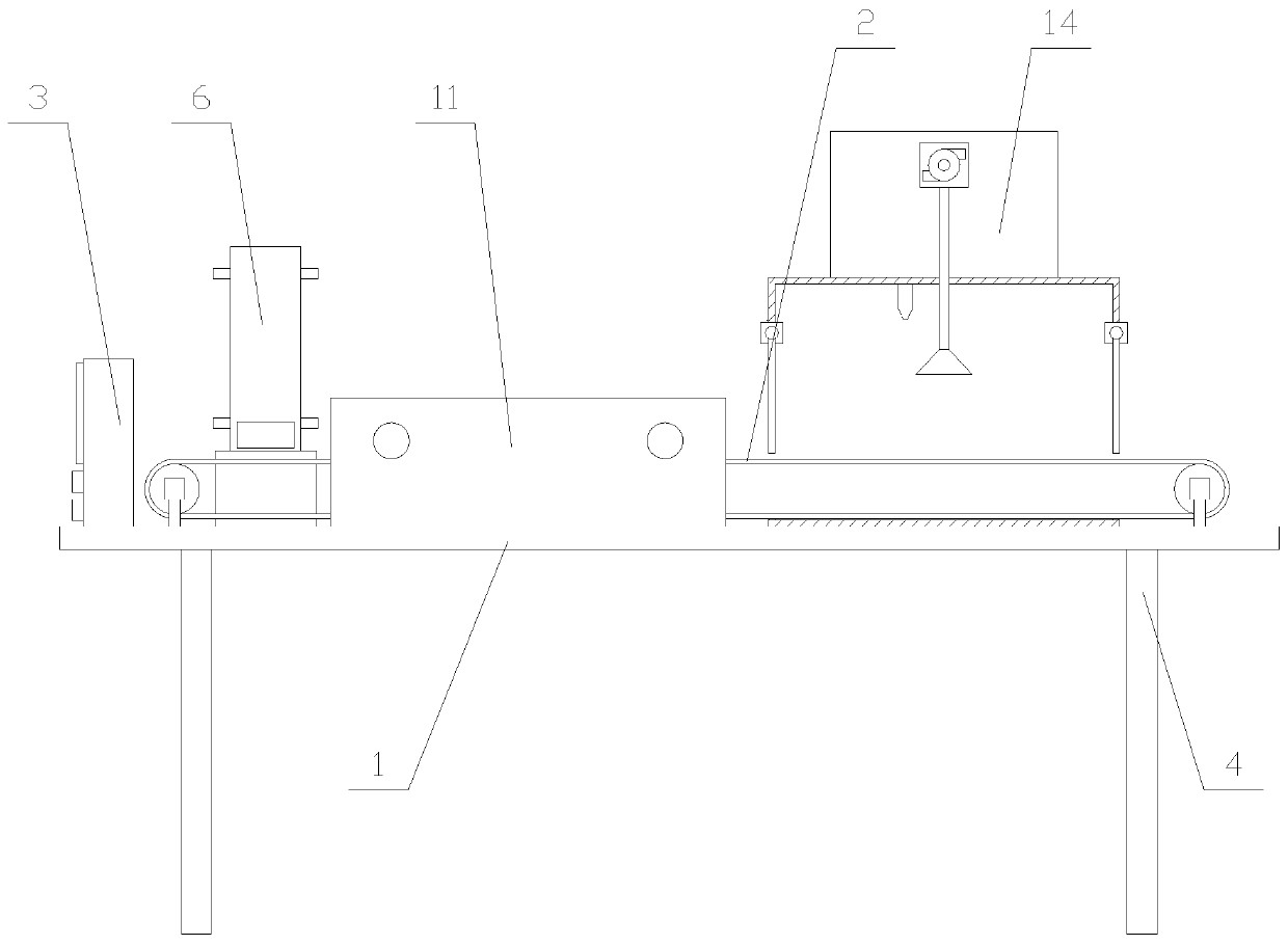
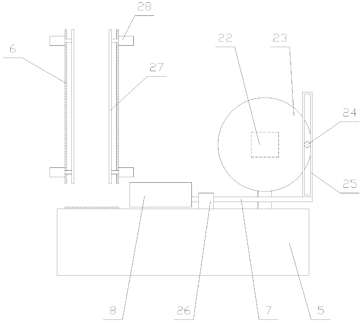
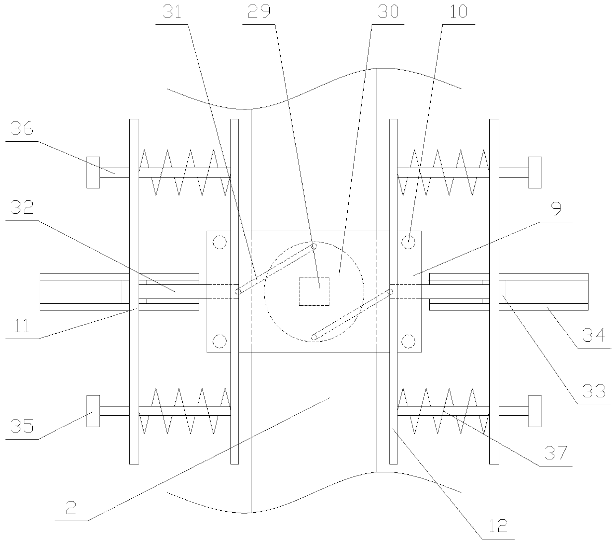
[0025] Such as figure 1 As shown, an automatic spraying system with correction function for workpiece processing, including a workbench 1, a supply mechanism, a correction mechanism, a spraying mechanism, a conveyor belt 2, a controller 3 and four legs 4, the four legs 4 are respectively fixed Below the four corners of the workbench 1, the controller 3, the conveyor belt 2, the supply mechanism, the straightening mechanism and the spraying mechanism are all arranged above the workbench 1, and the supply mechanism, the straightening mechanism and the spraying mechanism are arranged along the conveyor belt 2 Set in sequence, the controller 3 is provided with a ...


PUM


Abstract

The invention relates to an automatic spraying system with a correcting function for workpiece processing. The system comprises a workbench, a supply mechanism, a correcting mechanism, a spraying mechanism, a conveying belt, a controller and four supporting legs; the supply mechanism comprises a fixed block, a supply pipe, a pushing assembly and two adjusting assemblies, wherein the pushing assembly comprises a driving unit, a reciprocating rod and a pushing block; and the correcting mechanism comprises a supporting block, a power assembly, two correcting assemblies and four supporting rods, wherein the power assembly comprises a moving plate, a correcting plate and two buffering units. According to the automatic spraying system with the correcting function for workpiece processing, workpieces are automatically placed on the conveying belt one by one through the supply mechanism, and operators do not need to manually place the workpieces, so that the working time of the workers is shortened, and the labor cost is reduced; and moreover, the position of the workpieces on the conveying belt can be corrected through the correcting mechanism, thus facilitating the accurate spraying of nozzles, ensuring the spraying quality, and improving the practicability of the system.

Description

technical field [0001] The invention relates to the field of spraying equipment, in particular to an automatic spraying system with a correction function for workpiece processing. Background technique [0002] Automatic spraying machine is a professional term for automatic spraying machine. It is aimed at the current painting process and processing industry. It can be completed automatically, and can replace the mold or clean the mold at the same time, clean the spray gun, and is designed with a safety door, dust cover and The protective window isolates paint dust in the spray booth, avoids the adverse effects of paint dust on the operator, improves product quality, greatly improves production efficiency, reduces raw material consumption costs, improves the working environment of employees, protects the health of employees, and solves the problem of environmental pollution to the outside world. The problem of environmental pollution embodies the three characteristics of high...

Claims


Application Information

Patent Timeline
Patent Type & Authority Applications(China)
IPC IPC(8): B05B13/02B05B12/32B05B16/40
CPCB05B12/32B05B13/0221B05B16/40
Inventor 吴金富
Owner 扬州健松涂装材料有限公司
Learn More