Laser welding method

A technology of laser welding and laser beam, which is applied in the direction of laser welding equipment, welding equipment, welding/welding/cutting items, etc., can solve the problems of reduced quality and strength of welded parts, and achieve the effect of suppressing porosity and reducing productivity

Active Publication Date: 2019-12-13
TOYOTA JIDOSHA KK
View PDF11 Cites 2 Cited by
  • Summary
  • Abstract
  • Description
  • Claims
  • Application Information

AI Technical Summary

Problems solved by technology

) remains in the welded part, so the quality (mainly strength) of the welded part is reduced

Method used


Image

  • Laser welding method
  • Laser welding method
  • Laser welding method

Examples


experiment example

[0092] Next, an experimental example performed to confirm the effect of the laser welding method of this embodiment will be described.

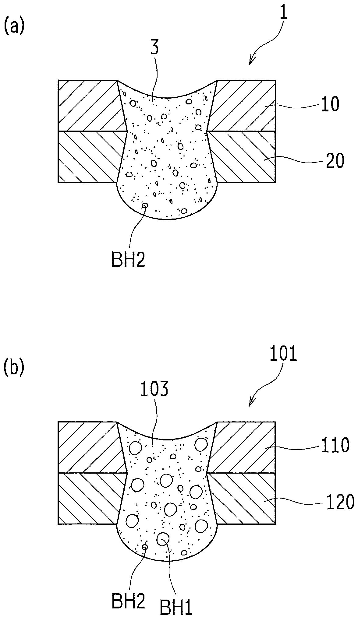
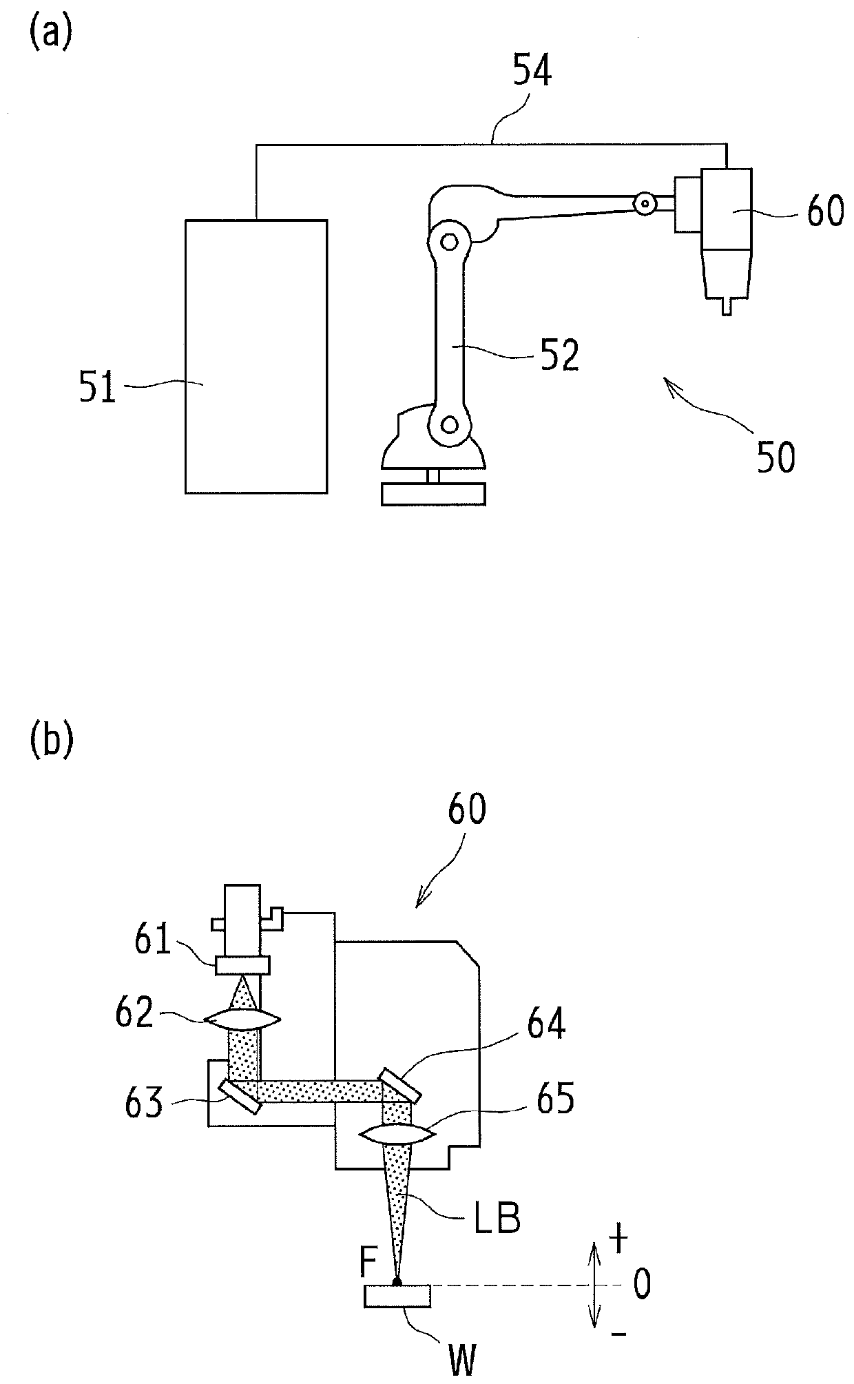
[0093] In the experimental example, such as Figure 8 As shown, an aluminum alloy plate 10 (110) with a width of 30 mm and a length of 100 mm and an aluminum alloy casting plate 20 (120) are placed so that the entire area in the width direction overlaps, and a square area of ​​30 mm in the length direction from the top Overlapping was carried out, and laser beam LB was irradiated to the center of the overlapping portion 5 (105), thereby manufacturing a test piece in which the aluminum alloy plate 10 (110) and the aluminum alloy casting plate 20 (120) were overlap-welded . In addition, the experimental example in which the said melting path and the said stirring path were implemented at the time of irradiation of the laser beam LB was made into the example of this invention, and the experimental example in which only the said melting path was...


PUM


Abstract

An object of the present invention is to provide a laser welding method for lap welding of a plurality of metal plates including an aluminum alloy casting, in which generation of relatively large blowholes in a welding part is reduced while decrease in productivity is reduced. As a means for solving the problem, a laser welding method for lap welding, using a laser beam (LB), of a plurality of metal plates (10, 20) including an aluminum alloy cast plate (20) is provided, which includes: a melting path of scanning and irradiating circularly a superimposed part (5) of the aluminum alloy plate (20) and the aluminum alloy cast plate (20) with a first laser beam (LB1) to form a molten pool (7) of the molten aluminum alloy plate (10) and the molten aluminum alloy cast plate (20); and a stirringpath of scanning and irradiating circularly the molten pool (7) with a second laser beam (LB2) having a scanning speed (V2) faster than a scanning speed V1 of the first laser beam (LB1) to stir the molten pool (7).

Description

technical field [0001] The present invention relates to a laser welding method, and more particularly to a laser welding method for overlapping and welding a plurality of metal plates including an aluminum alloy casting by using a laser beam. Background technique [0002] It is generally accepted that aluminum alloy castings are generally less suitable for welding than aluminum alloys formed by rolling or the like. The reason is that when welding an aluminum alloy casting as a material to be welded, a large amount of gas that is forced to dissolve in the aluminum alloy casting during casting appears as large bubbles in the melting zone, and the gas in the melting zone Large air bubbles that are not discharged before solidification remain in the welded portion as large pores (also called voids), and thus the quality (mainly strength) of the welded portion decreases. [0003] Therefore, for example, Patent Document 1 discloses a technique of irradiating a laser beam to a molt...

Claims


Application Information

Patent Timeline
Patent Type & Authority Applications(China)
IPC IPC(8): B23K26/21B23K26/00B23K26/40
CPCB23K26/21B23K26/00B23K26/40B23K26/082B23K26/22B23K26/32B23K2103/10B23K26/032B23K26/0648B23K26/073
Inventor 日置亨小仓修平川喜田笃史中田光纪后藤崇志河合亮佑
Owner TOYOTA JIDOSHA KK
Why Eureka
Try Eureka