
High-temperature-resistant and impact-resistant slag well

An impact-resistant and high-temperature-resistant technology, applied in the field of high-temperature and impact-resistant slag wells, can solve the problems of high construction process requirements, high-temperature material leakage, connection failure, etc., and achieves easy large-scale manufacturing and installation, reliable thermal expansion, and good thermal insulation performance. Effect

Pending Publication Date: 2019-12-13
QINGDAO DANENG ENVIRONMENTAL PROTECTION INC
View PDF0 Cites 0 Cited by
  • Summary
  • Abstract
  • Description
  • Claims
  • Application Information

AI Technical Summary

Problems solved by technology

[0002] Traditional slag wells have the following disadvantages: First, the expansion joints of traditional slag wells are water-sealed. During work, a large amount of water evaporates, and ash and slag materials will fly into and block the water-sealed tank, causing failures and difficult maintenance. Water vapor can also cause equipment corrosion, pollute the environment, and consume a lot of energy
Refractory castables have a certain shelf life, the construction requires special mechanical mixing, the construction time is long, and the construction technology requirements are high
The third is that the discharge port of the traditional slag well is directly connected to the next-level conveying equipment. The slag well support is located in the middle of the conical shell. The slag well outlet has a certain amount of thermal expansion. Thermal expansion will backlog the next-level conveying equipment, which will seriously lead to failure of the connection , there is a potential safety hazard of high-temperature material leakage

Method used


Image

  • High-temperature-resistant and impact-resistant slag well
  • High-temperature-resistant and impact-resistant slag well
  • High-temperature-resistant and impact-resistant slag well

Examples


Embodiment Construction

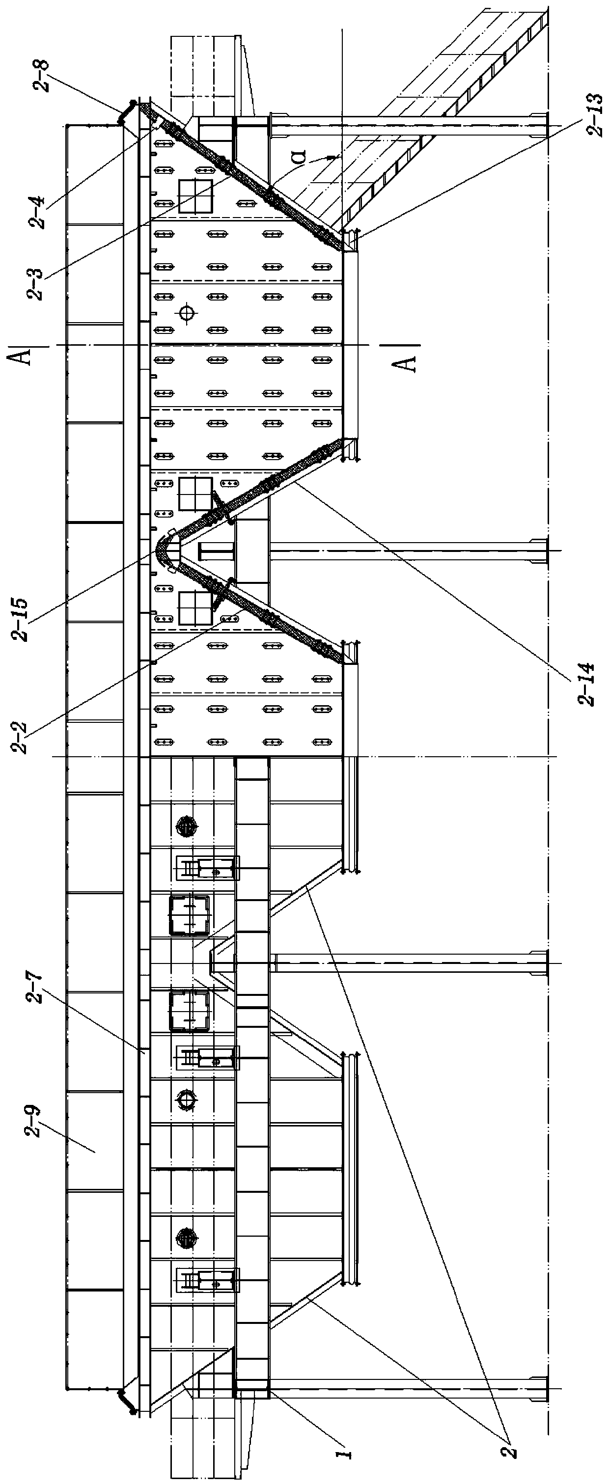
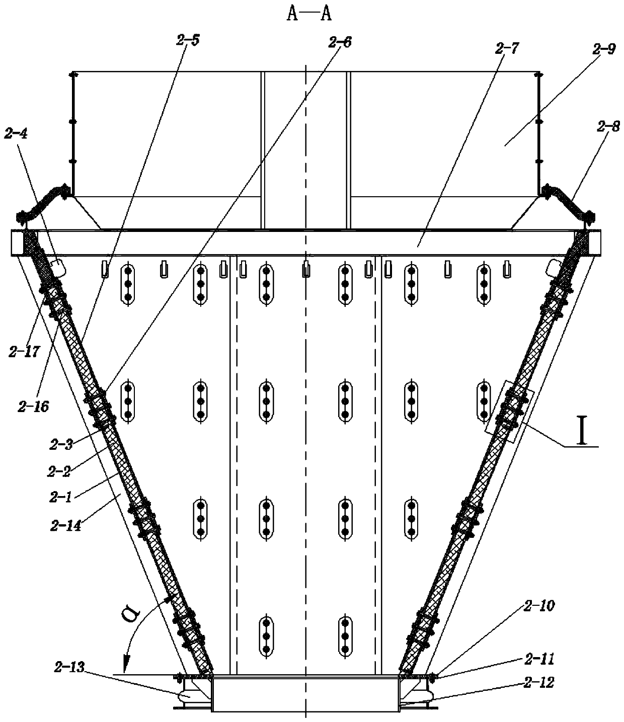
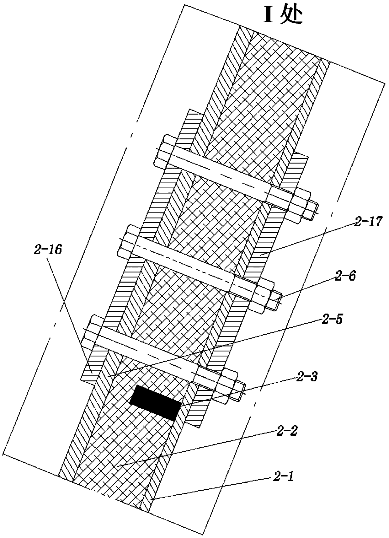
[0034] exist Figure 1 to Figure 6 Among them, the high-temperature resistant and impact-resistant slag well of the present invention includes an impact-resistant reinforced bracket 1, several conical hoppers 2 that are installed on the reinforced bracket and connected by arc-shaped middle beams 2-15 at the feed inlet; The conical hopper 2 described above includes a conical shell 2-1, a thermal insulation 2-2 installed on the inner wall of the conical shell, an anti-shock frame 2-2 located inside the thermal insulation and fixed on the inner wall of the conical shell 3. The hooks 2-4 installed on the inner wall of the upper part of the conical shell are laid on the surface of the heat preservation part and hung on the groove of the hook through the installation holes. Several inner anti-shock plates with different shapes and overlapping each other form the inner cone 2-5, Fasteners 2-6 for fastening the inner backing plate 2-16, the inner impact plate, the heat preservation pi...


PUM


Abstract

The invention provides a high-temperature-resistant and impact-resistant slag well. The high-temperature-resistant and impact-resistant slag well comprises reinforced supports and a plurality of conical hoppers mounted on the reinforced supports and connected with through arc-shaped middle cross beams at feed ports. Each conical hopper comprises a conical shell, heat insulation parts, impact-resistant brackets fixed to the inner wall of the conical shell, hooks mounted on the inner wall of the upper portion of the conical shell, a plurality of different shapes of inner impact-resistant plateslaid on the surfaces of the heat insulation parts, suspended to grooves of the hooks through mounting holes and overlapped and connected to form an inner conical body, fasteners, an upper ring beam mounted on the conical shell, high-temperature expansion joints mounted above the upper ring beam, a feed port sealing body, a hollow base plate mounted at the bottom of the conical shell, a flange, a discharge port body mounted on the flange, outlet high-temperature expansion joints and a reinforced steel frame. The high-temperature-resistant and impact-resistant slag well is resistant to high temperature and impact, high in strength, long in service life, easy to manufacture and install in large scale, good in heat insulation performance and reliable in heat expansion and can be extensively applied to a slag conveying system of a coal-fired power plant.

Description

technical field [0001] The invention relates to a high-temperature-resistant and impact-resistant slag well, which can be widely used in slag conveying systems of coal-fired power plants. Background technique [0002] Traditional slag wells have the following disadvantages: First, the expansion joints of traditional slag wells are water-sealed. During work, a large amount of water evaporates, and ash and slag materials will fly into and block the water-sealed tank, causing failures and difficult maintenance. Water vapor can also cause equipment corrosion, pollute the environment, and consume a lot of energy. The second is that the conical shell of the traditional slag well is paved with refractory castables inside for heat preservation and resistance to high-temperature material erosion. Since the maintenance time of the boiler is much shorter than the maintenance time of the refractory castable, and the impact of high-temperature ash material, the life of the refractory ca...

Claims


Application Information

Patent Timeline
Patent Type & Authority Applications(China)
IPC IPC(8): B65D90/12B65D90/02B65D90/00B65D88/26
CPCB65D90/12B65D90/02B65D90/00B65D88/26
Inventor 李蜀生蒋泽友李智张光荣孙智程于永强姜雯昕姜国琼王川川李小庆徐伟
Owner QINGDAO DANENG ENVIRONMENTAL PROTECTION INC
Learn More