Clamping device and clamping method

A clamping device and fixture technology, which is applied in the direction of transportation and packaging, conveyor objects, etc., can solve the problems of reduced work efficiency, frequent adjustment of movement distance, damage to substrate substrates, etc., to achieve high clamping accuracy and improve clamping accuracy. Maintain work efficiency and avoid damage

Inactive Publication Date: 2019-12-13
WUHAN CHINA STAR OPTOELECTRONICS TECH CO LTD
View PDF8 Cites 0 Cited by
  • Summary
  • Abstract
  • Description
  • Claims
  • Application Information

AI Technical Summary

Problems solved by technology

[0003] Before the fixture clamps the substrate, the engineer will determine the coordinates that the fixture needs to reach the predetermined position each time according to the position of the substrate, and then calculate the movement distance of the fixture, but the movement distance of the fixture will not be adjusted frequently. If there is a slight difference in the position of the substrate, the fixture will not be able to accurately clamp the substrate and cause damage to the substrate, resulting in an increase in production costs and a decrease in work efficiency

Method used


Image

  • Clamping device and clamping method
  • Clamping device and clamping method
  • Clamping device and clamping method

Examples


Embodiment Construction

[0032] In order to make the technical problems, technical solutions and beneficial effects to be solved by the present invention clearer, the following further describes the present invention in detail with reference to the accompanying drawings and embodiments. It should be understood that the specific embodiments described here are only used to explain the present invention, but not to limit the present invention.

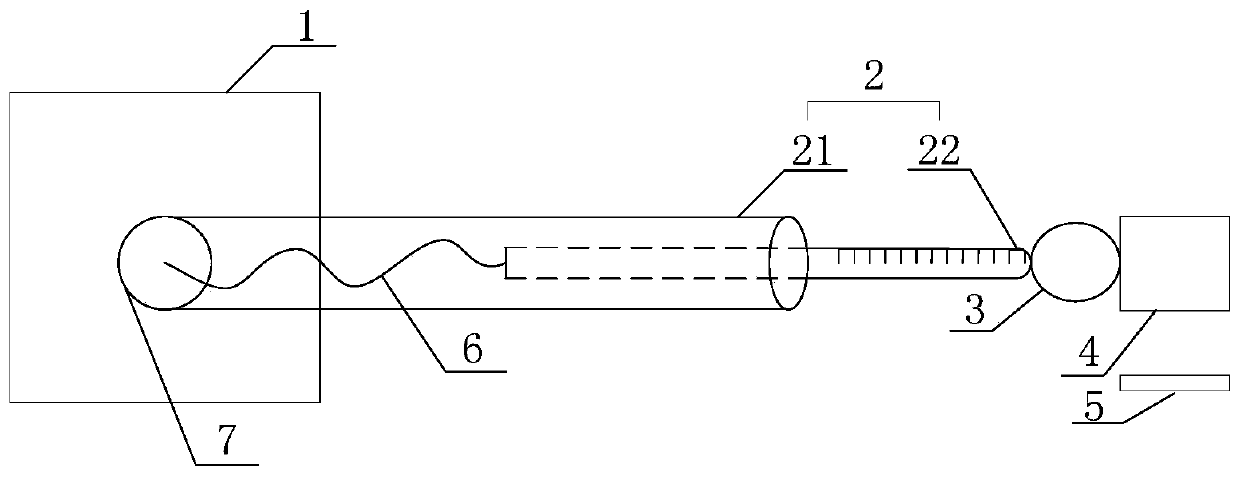
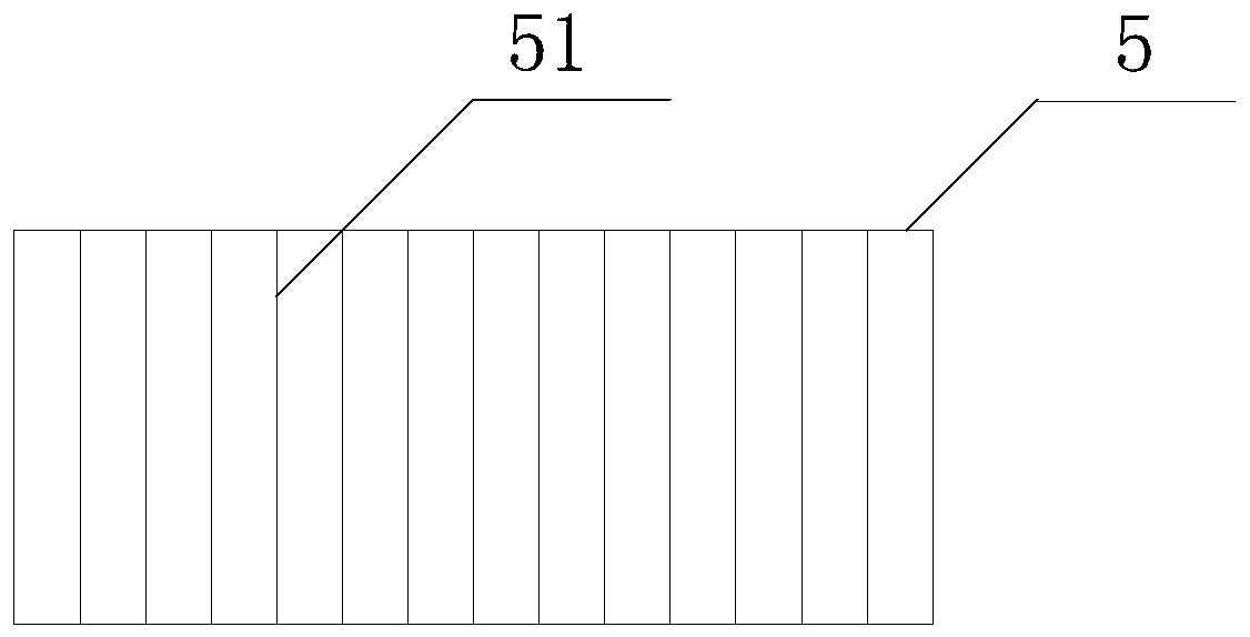
[0033] See figure 1 , figure 1 It is a schematic diagram of the structure of the clamping device provided by the embodiment of the present application. The clamping device includes a base 1, a telescopic rod 2, a clamp 3, a sensor 5, and a controller (not shown in the figure). One end of the telescopic rod 2 is fixedly connected to the base 1, and the clamp 3 is used for Clamp the target 4, which is fixed on the other end of the telescopic rod 2. When the telescopic rod 2 is in a telescopic motion, the clamp 3 drives the target 4 to move, and the sensor 5 is used to...


PUM


Abstract

The invention relates to a clamping device and a clamping method. The clamping device comprises a base, a telescopic rod, a clamp, a sensor and a controller, wherein one end of the telescopic rod is fixedly connected with the base, the clamp is used for clamping a target object, and the clamp is fixed on the other end of the telescopic rod; the clamp drives the target object to move when the telescopic rod performs telescopic motion; and the sensor is used for detecting an initial position of the target object, and the controller is used for determining the telescopic length of the telescopicrod according to the initial position and then controlling the telescopic rod to perform telescopic motion according to the telescopic length. The clamping device and the clamping method have the beneficial effects that the initial position of a substrate is detected through the sensor, and the telescopic rod is used for controlling the clamp to move to the initial position to clamp the substrate,so that the substrate flowing from the upstream is accurately clamped wherever the substrate move, the clamping precision is high, damage to the substrate can be effectively avoided, and the clampingworking efficiency is improved.

Description

【Technical Field】 [0001] This application relates to the liquid crystal panel industry, and more specifically, to a clamping device and a clamping method. 【Background technique】 [0002] With the continuous development and advancement of machines in the LCD industry, people have higher and higher requirements for machines. The substrates are used for clamping during the transfer and manufacturing process. After the substrate enters the machine table, the clamp will clamp the substrate so that the substrate can be accurately transferred to the next unit or perform a rotation operation. The clamp plays a role in adjusting the position of the substrate during the transfer process of the substrate, so that the substrate is in the transfer process. In, the location does not change. [0003] Before the fixture clamps the substrate, the engineer will determine the coordinates of the fixture each time the fixture needs to reach the predetermined position according to the position of the s...

Claims


Application Information

Patent Timeline
IPC IPC(8): B65G47/91
CPCB65G47/914
Inventor 年婷陈沈
Owner WUHAN CHINA STAR OPTOELECTRONICS TECH CO LTD
Why Eureka
Try Eureka