Tool clamping assembly

A technology for clamping and assembly, applied in the direction of clamping, positioning devices, clamping devices, etc., can solve the problems of unstable clamping, increased enterprise costs, and unfavorable operations for operators, and achieve fast, accurate and reliable clamping, and improve the quality of clamping Clamping accuracy, reducing the effect of clamping time

Inactive Publication Date: 2018-11-23
刘高
View PDF0 Cites 0 Cited by
  • Summary
  • Abstract
  • Description
  • Claims
  • Application Information

AI Technical Summary

Problems solved by technology

[0002] At present, opportunities and challenges coexist in China's drilling tool manufacturing industry, but overall, the favorable factors for the development of the industry occupy a dominant position. The prospect of high-quality alloy demand is good. The geometric parameters of the drilling part of the tool have a great influence on the drilling efficiency and the quality of the processing. During the long-term drilling use, the drilling tool wears very Fast, in the conventional drilling tool, the whole tool needs to be exhausted or thrown away, which is not conducive to long-term use and cost reduction, but will increase some costs of the enterprise; drilling is a basic method of hole processing, and drilling is often It can be carried out on drilling machines and lathes, and can also be carried out on boring machines or milling machines; in the process of home processing, clamping and assembly are often required, but the positioning effect of general clamping components is not good, the clamping is unstable, and it is easy to fall off. Not conducive to the operator to operate

Method used


Image

  • Tool clamping assembly

Examples


Embodiment Construction

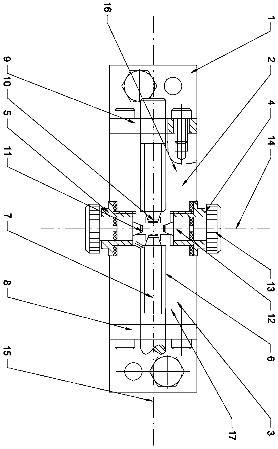
[0013] Such as figure 1 As shown, the purpose of the present invention is achieved in this way: a tool clamping assembly includes a base 1, the base 1 is arranged in a quadrilateral shape, and the two sides of the base 1 are respectively equipped with a baffle assembly, and the baffle assembly is arranged along the base 1. The center line is arranged symmetrically; the base 1 is equipped with a horizontal pressing assembly and a longitudinal pressing assembly, and the horizontal pressing assembly includes a left pressing assembly 2 and a right pressing assembly 3; the longitudinal pressing assembly includes a front pressing assembly 4 and the rear compression assembly 5, the left compression assembly 2 and the right compression assembly 3 are arranged symmetrically along the longitudinal centerline 15 of the base 1, and the front compression assembly 4 and the rear compression assembly 5 are arranged along the base The transverse center line 14 of 1 is symmetrically arranged; ...


PUM


Abstract

The invention relates to a tool clamping assembly and belongs to the field of tool processing. The tool clamping assembly comprises a base, wherein the base is of a quadrilateral shape; baffle plate assemblies are arranged at two sides of the base respectively in a matching manner; the baffle plate assemblies are symmetrically arranged along the central line of the base; the base is provided witha transverse pressing assembly and a longitudinal pressing assembly in a matching manner; the transverse pressing assembly comprises a left side pressing assembly and a right side pressing assembly; the longitudinal pressing assembly comprises a front side pressing assembly and a rear side pressing assembly; the left side pressing assembly and the right side pressing assembly are symmetrically arranged along the longitudinal central line of the base; the front side pressing assembly and the rear side pressing assembly are symmetrically arranged along the transverse central line of the base; acamping assembly placement part is arranged at the center of the base. The tool clamping assembly provided by the invention can be used for rapidly, accurately and firmly clamping a tool needing to beprocessed; the clamping accuracy is improved, the clamping time is reduced and the working efficiency is improved.

Description

technical field [0001] The invention relates to the field of tool processing, in particular to a clamping assembly for tool processing. Background technique [0002] At present, opportunities and challenges coexist in China's drilling tool manufacturing industry, but overall, the favorable factors for the development of the industry occupy a dominant position. The prospect of high-quality alloy demand is good. The geometric parameters of the drilling part of the tool have a great influence on the drilling efficiency and the quality of the processing. During the long-term drilling use, the drilling tool wears very Fast, in the conventional drilling tool, the whole tool needs to be exhausted or thrown away, which is not conducive to long-term use and cost reduction, but will increase some costs of the enterprise; drilling is a basic method of hole processing, and drilling is often It can be carried out on drilling machines and lathes, and can also be carried out on boring mac...

Claims


Application Information

Patent Timeline
IPC IPC(8): B23Q3/06B23Q3/08
CPCB23Q3/062B23Q3/08B23Q2703/04
Inventor 刘高
Owner 刘高
Why Eureka
Try Eureka