
A device for adjusting the air flow of the edge suction thread of the laminating machine

A technology of airflow adjustment and laminating machine, which is applied in the direction of conveyors, transportation and packaging, and conveying bulk materials. It can solve problems such as blockage in pipelines, achieve the effects of improving reliability, ensuring reliability, and accurately adjusting the size of the wind force.

Active Publication Date: 2021-06-18
ANHUI THE PARKSON SOURCE PACKAGING MATERIALS
View PDF8 Cites 0 Cited by
  • Summary
  • Abstract
  • Description
  • Claims
  • Application Information

AI Technical Summary

Problems solved by technology

[0005] Aiming at the deficiencies of the prior art, the present invention provides a device for regulating the air flow of the edge yarn of the laminating machine, which solves the problem that different line speeds and widths of the edge yarn require different wind forces to control the blowing of the edge yarn, and the wind force is too small. If the side wire cannot be sucked, it will be blocked in the pipe

Method used


Image

  • A device for adjusting the air flow of the edge suction thread of the laminating machine
  • A device for adjusting the air flow of the edge suction thread of the laminating machine
  • A device for adjusting the air flow of the edge suction thread of the laminating machine

Examples


Embodiment 1

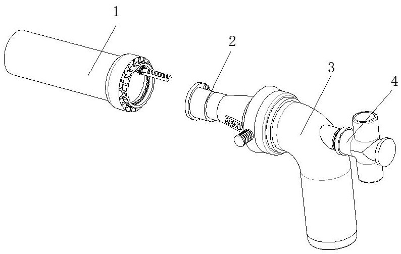
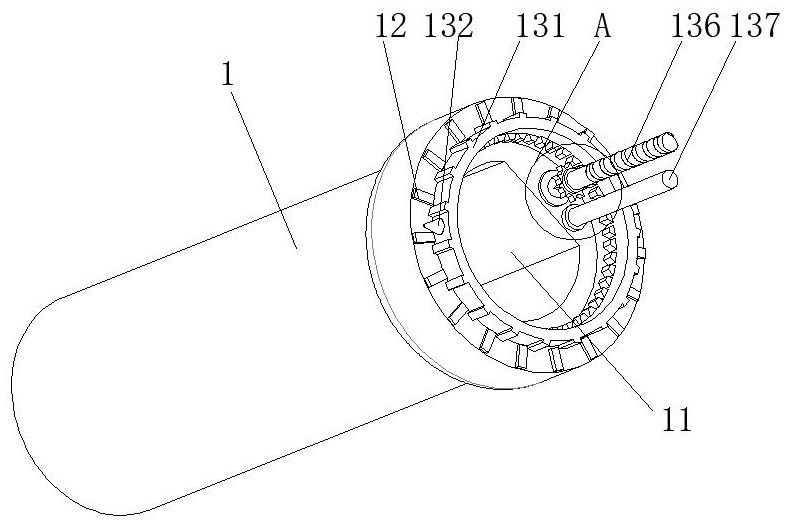
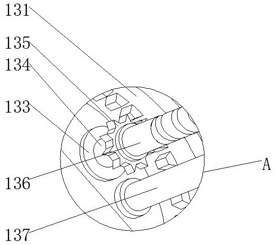
[0032] Such as figure 1 , 4As shown in , 5, the embodiment of the present invention provides a device for adjusting the air flow of the edge suction thread of the laminating machine. The outer surface of the first cone section 23 is fixedly installed with a limiting plate 231, and the outer surface of the limiting plate 231 is provided with holes. The first Both sides of the inner wall of the cone section 23 are fixedly equipped with a guide structure 232, the guide structure 232 includes a sleeve 2321, the inside of the first cone section 23 is fixedly installed with a sleeve 2321, the inner wall of the sleeve 2321 is slidably connected with a slide rod 2322, and the slide The outer surface of the rod 2322 is fixedly sleeved with a buffer spring 2323 , and the end of the slide rod 2322 away from the casing 2321 is rotatably connected to a guide wheel 2324 through the shaft 134 .

Embodiment 2

[0034] Such as figure 1 , 4 As shown in , 5, the embodiment of the present invention provides a device for adjusting the air flow of the edge suction thread of the laminating machine. The outer surface of the first cone section 23 is fixedly installed with a limiting plate 231, and the outer surface of the limiting plate 231 is provided with holes. The first Guide rails are fixedly installed on both sides of the inner wall of the cone section 23 .


PUM


Abstract

The invention provides an airflow regulating device for edge-absorbing threads of a laminating machine, and relates to the technical field of airflow regulating devices for edge-absorbing threads of a laminating machine. The airflow regulating device for edge-absorbing threads of a laminating machine includes an outer cylinder, and a guide plate is arranged inside the outer cylinder , the outer surface of the guide plate is fixedly equipped with an operating structure, the outer surface of the outer cylinder is located on one side of the operating structure, and a dial is fixedly installed, one side of the outer cylinder is fixedly installed with an adjustment structure, and one side of the adjustment structure is fixedly installed with a hair dryer , A suction edge cylinder is fixedly inserted inside the hair dryer. In the process of recycling waste edge yarns, the present invention can obtain suitable wind force by adjusting the position of the first cone section, so as to ensure real-time adjustment under the conditions of different widths of edge yarns, and improve the reliability of edge yarn suction. The edge thread inhaled from the edge suction cylinder passes through the outer cylinder smoothly, and the inner wall of the second tapered section is set in the shape of a trumpet, which in turn reduces the movement resistance of the edge thread and ensures the reliability of the edge suction thread.

Description

technical field [0001] The invention relates to the technical field of an airflow regulating device for edge-absorbing threads, in particular to an airflow regulating device for edge-absorbing threads of a laminating machine. Background technique [0002] The laminating machine can be divided into two categories: instant coating laminating machine and pre-coating laminating machine. It is a special equipment for paper, board and film lamination. It is pressed together by a rubber roller and a heating roller to form a paper-plastic product. [0003] In the online waste edge recycling system of the laminating machine, the reliability of the edge suction yarn directly affects the operation reliability of the whole machine. In the case of the same line speed and edge width, a stable wind force is required to ensure the suction of the edge thread, but different line speeds and edge thread widths require different wind forces to control the blowing of the edge thread, and the win...

Claims


Application Information

Patent Timeline
Patent Type & Authority Patents(China)
IPC IPC(8): B65G53/24B65G53/66B65G53/34B32B38/00
CPCB32B38/00B65G53/24B65G53/34B65G53/66
Inventor 刘文峰黄怡晴刘家岐
Owner ANHUI THE PARKSON SOURCE PACKAGING MATERIALS
Learn More