Recovery and treatment equipment for sewage

A technology of sewage recovery and treatment equipment, applied in water/sewage treatment, water/sewage multi-stage treatment, water/sludge/sewage treatment, etc. Simple, easy to operate, and the effect of protecting the environment

Inactive Publication Date: 2019-12-13
杨桂英
View PDF0 Cites 4 Cited by
  • Summary
  • Abstract
  • Description
  • Claims
  • Application Information

AI Technical Summary

Problems solved by technology

Although the traditional sewage recovery filter can effectively recycle domestic sewage, but because domestic sewage often contains some floating and sediment impurities, these things can easily cause the sewage recovery filter to clog, thereby affecting the filtering effect

Method used


Image

  • Recovery and treatment equipment for sewage
  • Recovery and treatment equipment for sewage
  • Recovery and treatment equipment for sewage

Examples


Embodiment 1

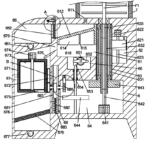
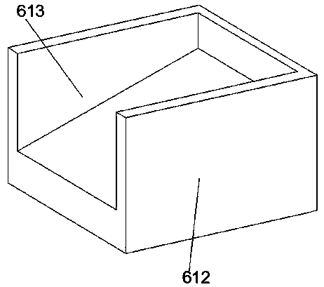
[0038] When sewage recycling is required, the first motor 641 drives the second outer key shaft 642 to rotate, and then the second outer key shaft 642 drives the inner key rotating sleeve 632, and the inner key rotating sleeve 632 drives the first outer key shaft 633 to rotate , and the first external key shaft 633 drives the mixer 71 to rotate, and then realizes the rapid mixing reaction of the sewage and the medicament in the mixing reaction tank 7, and then through the opening of the feed valve 611, and then realizes making the mixing reaction tank 7 The mixed sewage enters the slope groove 613 through the feed valve 611, and flows into the water inlet 662 through the slope groove 613. After being filtered by the sewage filter plate 6622, the filtered sewage enters the sewage collection chamber 66 and is discharged through the upper sewage. The pipe 661 is discharged, and the reacted sewage impurities are retained in the slope groove 613, and then the second motor 622 is use...

Embodiment 2

[0040] The second motor 622 controls the reverse rotation of the adjusting screw 623, so that the first pull cord 682 is in a relaxed state, and then the tooth condition 681 faces the top direction of the inner sliding chamber 68 because the tooth condition 681 is pressed by the second spring 683 Sliding, at this time, the tooth condition 681 drives the fifth gear 684 to rotate in reverse until the adjusting slider 621 returns to the initial position, and then the adjusting slider 621 drives the lifting sliding block 631 to return to the initial position, and at the same time, the lifting and sliding The block 631 drives the movable slider 612 to return to the initial position, and at the same time, the centrifugal filter bucket 671 is rotated to the initial position, so that the dehydrated sewage sediment impurities in the centrifugal filter bucket 671 fall on the inclined filter guide plate 676 and then pass through the discharge port 678 Drain, the water liquid produced duri...


PUM


Abstract

The invention discloses recovery and treatment equipment for sewage. The recovery and treatment equipment comprises a sewage recovering equipment body and a mixed reaction barrel fixedly arranged on the top of the sewage recovering equipment body, wherein a movable inner cavity is formed in the sewage recovering equipment body; a driving inner cavity is formed in the lower side of the movable inner cavity; a sewage collection cavity is formed in the left side of the movable inner cavity; a movable sliding block is arranged in the movable inner cavity; a lifting sliding cavity extending downwards is formed in the right side wall of the movable inner cavity in a communicating mode; the tail end of the bottom of the lifting sliding cavity is communicated with the driving inner cavity; a lifting adjusting mechanism used for controlling the movable sliding block to move up and down is arranged in the lifting sliding cavity; a centrifugal dewatering mechanism is arranged at the left side ofthe driving inner cavity and is connected with the lifting adjusting mechanism in a power fit mode; a hammering groove is formed in the bottom wall of the movable inner cavity; and a sewage filteringmechanism is arranged between the sewage collecting cavity and the movable inner cavity. The recovery and treatment equipment of the invention is convenient to operate and improved in sewage treatmentefficiency.

Description

technical field [0001] The invention relates to the technical field of environmental protection equipment, in particular to sewage recovery and treatment equipment. Background technique [0002] Sewage usually refers to certain polluted discharge water from domestic and production. Sewage mainly includes domestic sewage, industrial wastewater and initial rainwater. The main pollutants of sewage include pathogen pollutants, oxygen-consuming pollutants, plant nutrients and toxic pollutants. Wait. Most of the sewage in life is only slightly polluted and can be reused if filtered. Although the traditional sewage recovery filter can effectively recycle domestic sewage, but because domestic sewage often contains some floating and sediment impurities, these things can easily cause the sewage recovery filter to clog, thereby affecting the filtering effect. Contents of the invention [0003] The object of the present invention is to provide a sewage recovery treatment equipment f...

Claims


Application Information

Patent Timeline
Patent Type & Authority Applications(China)
IPC IPC(8): C02F9/04
CPCC02F1/00C02F1/001C02F2303/16
Inventor 杨桂英
Owner 杨桂英
Why Eureka
Try Eureka