835mm last-stage moving blade suitable for running under low-load working condition
A low-load, moving blade technology, applied in blade support elements, engine elements, machines/engines, etc., can solve problems such as inability to apply peak-shaving units, lack of availability, etc., to achieve optimal flow efficiency and strength, vibration characteristics, and vibration. Vibration problems are improved and blade dynamic stress is significantly reduced
- Summary
- Abstract
- Description
- Claims
- Application Information
AI Technical Summary
Problems solved by technology
Method used
Image
Examples
specific Embodiment approach 1
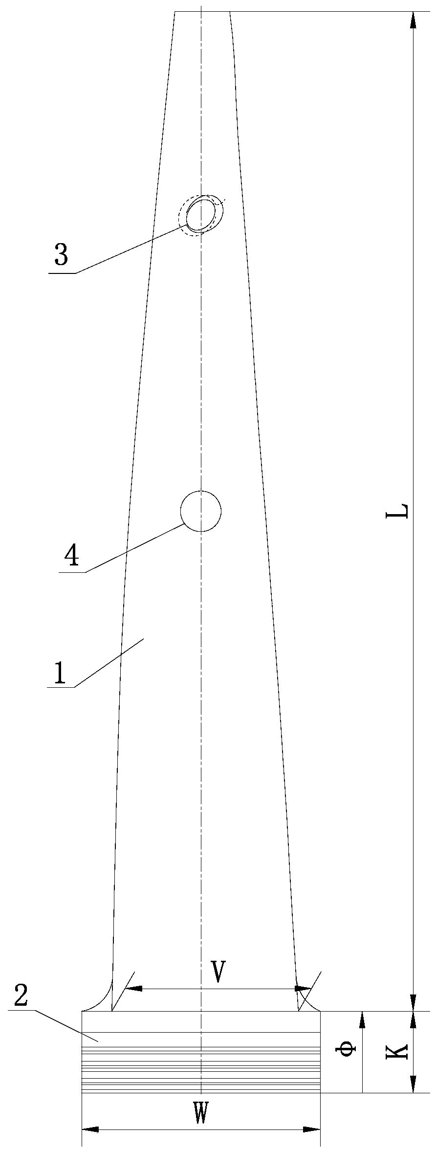
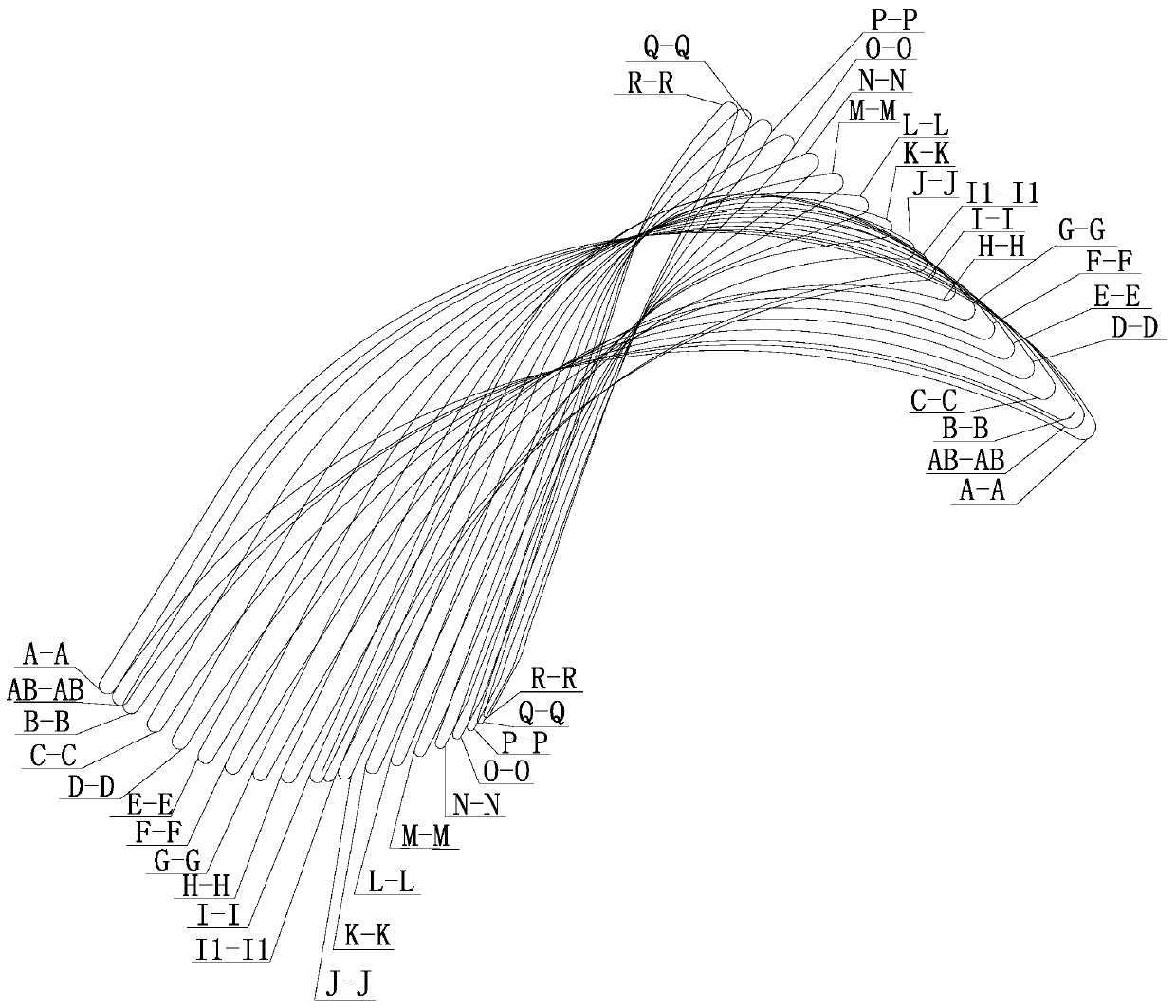
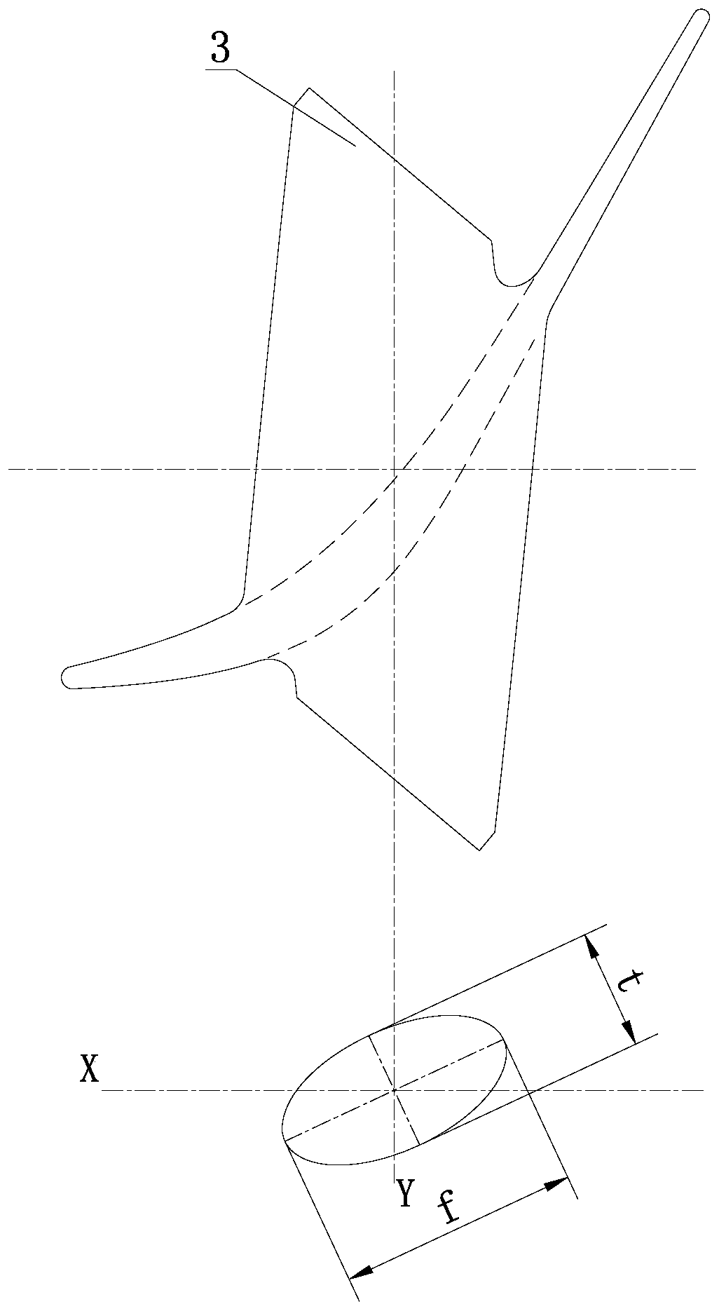
[0018] Specific implementation mode one: combine Figure 1-Figure 5 Describe this embodiment, an 835mm last-stage moving blade suitable for low-load operation in this embodiment includes a blade working part 1 and a blade root 2; it also includes boss ribs 3 and perforated ribs 4. Part 1, boss tie bar 3 and blade root 2 are forged together from top to bottom. The perforated tie bar 4 is located in the middle of the blade working part 1 and adopts a half-section form. The profile of the blade working part 1 is a variable cross-section twisted blade , there is relative torsion between two adjacent sections, the cross-sectional area of the blade working part 1 decreases gradually from the root to the top, the height L of the blade working part 1 is 835 mm, the root axial width V of the blade working part 1 is 160 mm, and the blade working part 1 root diameter of part 1 is 1700mm, and the exhaust area of blade working part 1 is 6.65m 2 , the blade root 2 is an arc-shaped fi...
specific Embodiment approach 2
[0020] Specific implementation mode two: combination figure 1 , Figure 5 , Figure 6 and Figure 7 To illustrate this embodiment, the variation range from the root axial width V of the blade working part 1 to the top axial width of the blade working part 1 is 160mm-40.739mm, and the variation range of the chord length b is 166.432mm-104.453mm , installation angle β y The range of change is 75.39°-28.34°, the range of maximum thickness T of the molding line is 18.98mm-6.14mm, the range of inlet angle α is 45.45°-152.04°, and the range of outlet angle θ is 33.1°-23.1° . By adopting the above structural parameters, the blades can be easily assembled while ensuring that the outer structure dimensions of the blades meet the design requirements. Other components and connections are the same as those in the first embodiment.
specific Embodiment approach 3
[0021] Specific implementation mode three: combination figure 1 , Figure 5 , Figure 6 and Figure 7 Describe this embodiment, the height L of blade working part 1 of this embodiment is respectively 0mm, 28mm, 49.4mm, 98.8mm, 148.1mm, 197.5mm, 246.9mm, 296.3mm, 345.7mm, 390mm, 410mm, 444.4mm, The axial width B of blade working part 1 corresponding to 493.8mm, 543.2mm, 592.6mm, 641.9mm, 693.1mm, 740.7mm, 790.1mm, 839.5mm are respectively: 160mm, 155.975mm, 152.882mm, 145.708mm, 138.439mm, 131.032 mm, 123.516mm, 115.91mm, 108.209mm, 100.395mm, 97.2118mm, 92.513mm, 84.574 mm, 76.611mm, 68.823mm, 61.495mm, 54.796mm, 48.885mm, 44.9739mm, corresponding The chord lengths b are respectively: 165.432mm, 162.53mm, 160.38mm, 155.626mm, 151.117mm, 146.763mm, 142.498mm, 138.2mm, 133.886mm, 129.644mm, 127.905mm, 125.565mm, 121.780mm, 318.3mm 115.296mm, 112.809mm, 110.672mm, 108.858mm, 105.514 mm, 104.453mm, the corresponding installation angle β y They are: 75.3852°, 73.755°, 72.4741°...
PUM
 Abstract
Description
Claims
Application Information
 - R&D
- Intellectual Property
- Life Sciences
- Materials
- Tech Scout
- Unparalleled Data Quality
- Higher Quality Content
- 60% Fewer Hallucinations
Browse by: Latest US Patents, China's latest patents, Technical Efficacy Thesaurus, Application Domain, Technology Topic, Popular Technical Reports.
© 2025 PatSnap. All rights reserved.Legal|Privacy policy|Modern Slavery Act Transparency Statement|Sitemap|About US| Contact US: help@patsnap.com


