
Compression-ignited IC engine and method of operation

a technology of combustion engine and combustion chamber, which is applied in the direction of machines/engines, electrical control, mechanical equipment, etc., can solve the problems of high nox emissions in the exhaust stream, engine damage, and spark-ignited engines that may be somewhat inefficient, and achieve low emissions and high efficiency

Inactive Publication Date: 2006-10-17
GM GLOBAL TECH OPERATIONS LLC
View PDF14 Cites 69 Cited by
  • Summary
  • Abstract
  • Description
  • Claims
  • Application Information

AI Technical Summary

Benefits of technology

The present invention provides a dual fuel injection system for a compression-ignition internal combustion engine that can operate in PCCI mode over a wide range of loads with high efficiency and low emissions. The system uses a primary fuel injector to provide a premixed fuel and air charge at the start of ignition, and a secondary fuel injector to deliver a highly homogeneous fuel and air mixture for controlled ignition and low emissions. The engine can transition between different modes of operation based on engine architecture and fuel ratio. The method of operation involves injecting fuel and air into the cylinder during the intake and compression strokes, and controlling the timing of the fuel injector to optimize engine performance. The invention allows for low emissions and high efficiency in a variety of engine loads and combustion modes.

Problems solved by technology

However, the spark-ignited engine may be somewhat inefficient since the compression ratio of the engine is kept to a lower than optimal level to avoid spark knock.
Spark knock occurs when the fuel and air mixture ignites independently of the spark plug and may cause engine damage.
These overly rich areas occur due to the non-homogeneity of the fuel and air charge occasioned by the lack of adequate premixing of the fuel and air upon ignition.
The compression-ignited engine, due to its locally stoichiometric combustion, combusts the fuel and air mixture at high temperatures causing high NOx emissions in the exhaust stream.
The expansion process occurs so quickly that the chemical reactions are frozen and the NOx quantities are unable to reach chemical equilibrium resulting in high engine-out NOx emissions.
This may lessen NOx formation and may also lead to decreases in efficiency and difficulties starting at cold temperatures.
The combination of high EGR rates and early SOI result in a long ignition delay period prior to the start of combustion (SOC).
The ignition delay period exceeds the fuel injection duration during PCCI combustion resulting in a premixed combustion event at the SOC.
As the engine load increases, the amount of heat released in the rapid premixed burning process becomes large enough to create excessive combustion noise.
This occurs even if there is sufficient premixing of the fuel and air during the ignition delay period.
Excessive combustion noise is objectionable to consumers; consequently, PCCI combustion has a low engine load limit.
Due to the low volatility inherent in diesel fuel, it is difficult to create a homogenous fuel and air mixture.
A conventional diesel fuel injector has a wide injector spray cone, and the early injection timing required for HCCI combustion may cause significant fuel impingement on the cylinder wall.
Fuel impingement on the cylinder wall inhibits the formation of a homogeneous fuel and air mixture and may cause fuel dilution of the lubricating oil.
This is typically an expensive endeavor that requires much experimentation and development to perfect.
This premature ignition can cause noise, poor performance, and engine damage in extreme cases.
This reduction in compression ratio will result in a decrease in efficiency.

Method used


Image

  • Compression-ignited IC engine and method of operation
  • Compression-ignited IC engine and method of operation

Examples


Embodiment Construction

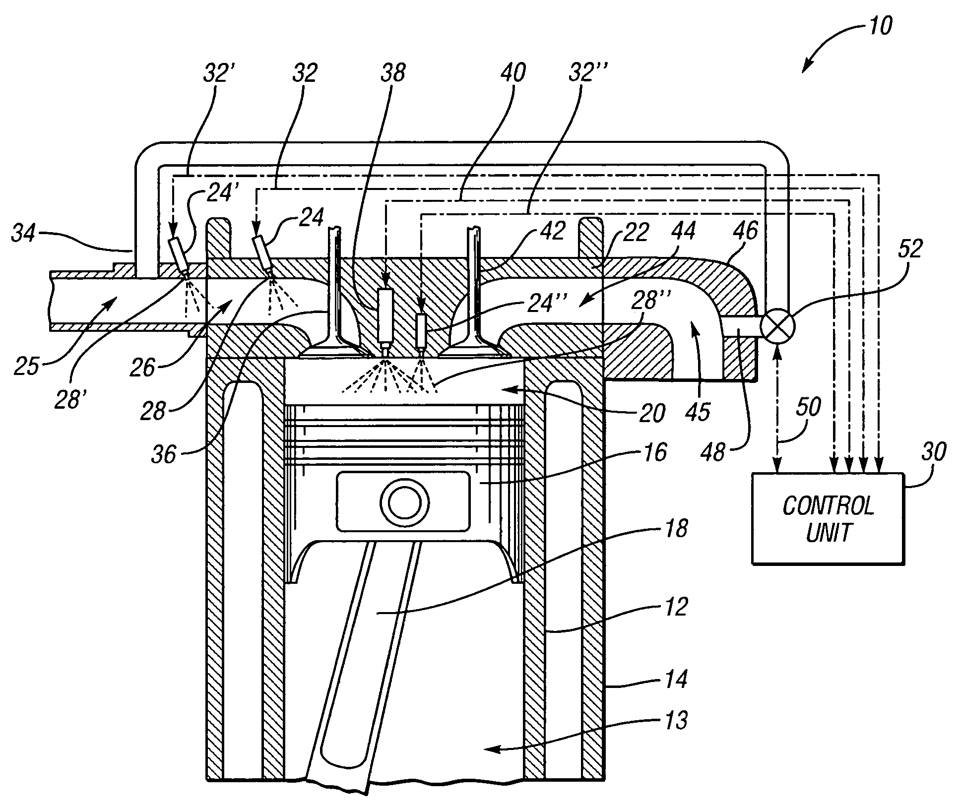
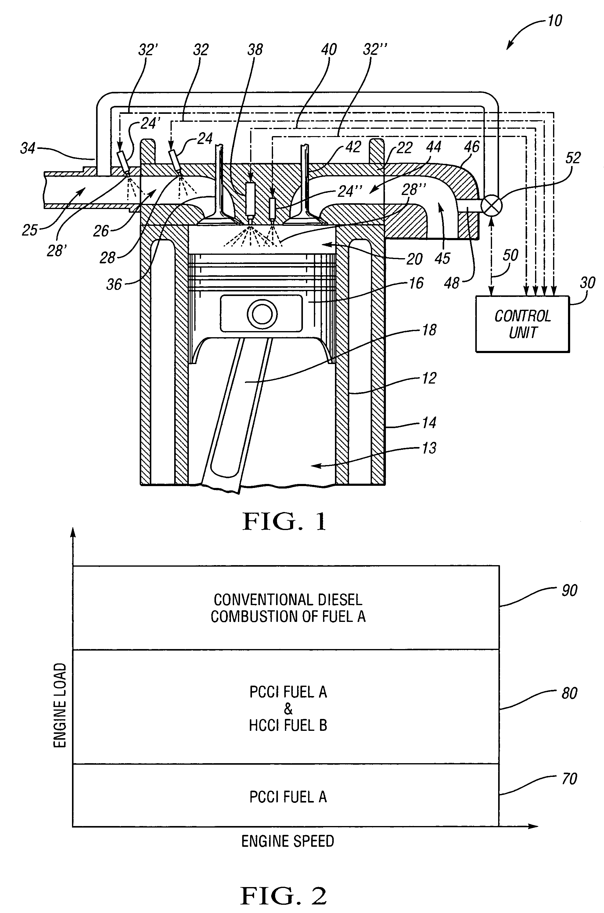
[0020]Referring to FIG. 1, this figure presents an improved compression-ignited internal combustion engine 10 that is capable of operating in a premixed charge compression ignition mode over a much greater range of engine load conditions without producing excessive noise, soot emissions, and NOx emissions. This expanded range is facilitated by the use a dual fuel injection strategy. The compression ignition internal combustion engine 10 is characterized by a cylinder liner 12 enclosed by a cylinder case 14 and defining a cylinder bore 13 which reciprocally houses a piston 16. The piston 16 is connected to one extreme of the connecting rod 18. When the piston 16 is near TDC of the compression stroke, the bowl in the piston 16 forms a combustion chamber 20 with the cylinder head 22.

[0021]During the intake stroke of piston 16, a measured amount of fuel B will flow from the secondary fuel injector 24 into the inlet port 26 defined by the cylinder head 22. The secondary fuel injector 24 ...


PUM


Abstract

The present invention is a compression ignition internal combustion engine and method of operation which expands the load limit of quietly operating a premixed charge compression ignition (PCCI) engine by injecting a secondary fuel B, in ratios lean of stoichiometric, either into the intake air stream or directly into the cylinder to form a homogeneous fuel B and air mixture. Near top dead center of the compression stroke, a PCCI-type direct injection of fuel A event is used to initiate combustion of both fuel A and B at the proper time. At low loads the combustion mode is characterized a PCCI-type with high EGR rates. At medium loads the combustion mode is that of homogeneous combustion of fuel B coupled with PCCI combustion of fuel A. At the highest loads the engine will revert to a conventional diesel combustion mode of fuel A to maintain power density.

Description

TECHNICAL FIELD[0001]The present invention relates to a compression ignition internal combustion engine having a dual fuel injection system and method of operation, thereby expanding the load range in which the compression-ignited engine can operate in premixed charge compression ignition (PCCI) mode without producing excessive amounts of oxides of nitrogen, soot, and noise.BACKGROUND OF THE INVENTION[0002]Internal combustion engines can generally be grouped into one of two classes, spark-ignited and compression-ignited engines. Spark-ignited engines typically operate by introducing a stoichiometric mixture of air and fuel into the cylinder of the engine. The piston then compresses this mixture, and at predetermined crankshaft angle, a spark plug will ignite the fuel and air mixture producing a flame front that propagates through the combustion chamber. The rapid increase in heat from the burned fuel triggers an increase in pressure which forces the piston downward in the cylinder. ...

Claims


Application Information

Patent Timeline
Patent Type & Authority Patents(United States)
IPC IPC(8): F02B7/00F02B13/00
CPCF02D19/081F02D41/0025F02D41/0057F02D41/3035F02D19/0649F02D19/0689F02D19/0692F02B1/12F02D19/08Y02T10/128Y02T10/36Y02T10/47Y02T10/12Y02T10/30Y02T10/40
Inventor WICKMAN, DAVID D.HERGART, CARL-ANDERS
Owner GM GLOBAL TECH OPERATIONS LLC
Learn More