Engine tail gas treatment system and treatment method

A technology for exhaust gas treatment and engine, which is applied in the direction of exhaust gas treatment, engine components, combustion engines, etc. It can solve the problems of high local temperature, shortened DPF service life, and burnout of DPF carrier, so as to achieve uniform PM distribution, improve uniformity, The effect of prolonging the service life

Active Publication Date: 2019-12-13
WEICHAI POWER CO LTD
View PDF10 Cites 6 Cited by
  • Summary
  • Abstract
  • Description
  • Claims
  • Application Information

AI Technical Summary

Problems solved by technology

However, when DPF active regeneration occurs (the main method of regeneration is to oxidize particles through high temperature), the local temperature on the DPF carrier is often too high, and the DPF carrier burns out and fails, which greatly shortens the service life of the DPF.

Method used


Image

  • Engine tail gas treatment system and treatment method
  • Engine tail gas treatment system and treatment method
  • Engine tail gas treatment system and treatment method

Examples


Embodiment Construction

[0032] In order to enable those skilled in the art to better understand the solution of the present invention, the present invention will be further described in detail below in conjunction with the accompanying drawings and specific embodiments.

[0033] In this article, terms such as "upper, lower, left, right" are established based on the positional relationship shown in the drawings, and the corresponding positional relationship may also change accordingly depending on the drawings. It is understood as an absolute limitation on the scope of protection; moreover, relative terms such as "first" and "second" are only used to distinguish one from another component with the same name, and do not necessarily require or No such actual relationship or order between these components is implied.

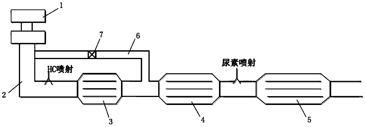
[0034] Please refer to figure 1 , figure 1 It is a schematic structural diagram of an engine exhaust treatment system disclosed in an embodiment of the present invention.

[0035] As sh...


PUM


Abstract

The invention discloses an engine tail gas treatment system and treatment method. The treatment system comprises an exhausting pipeline, a particle filter arranged on an exhausting path of the exhausting pipeline, a preceding stage treater located on the upstream of the particle filter, and a post stage treater located on the downstream of the particle filter. The treatment system is further provided with a waste gas branch. One end of the waste gas branch communicates with the portion, located on the upstream of the preceding stage treater, of the exhausting pipeline. The other end of the waste gas branch communicates with the portion, between the preceding stage treater and the particle filter, of the exhausting pipeline. The waste gas branch is provided with a bypass valve. According tothe system, in the driving regeneration process of the particle filter, the situation that due to the fact that the local temperature is too high, a carrier of the particle filter is burnt out easilyis avoided, and thus the service life of the particle filter is prolonged greatly.

Description

technical field [0001] The invention relates to the technical field of engines, in particular to an exhaust gas treatment system of a diesel engine. The invention also relates to the exhaust gas treatment method of the diesel engine. Background technique [0002] At present, diesel engines are widely used in automobiles, but at the same time, they are also facing the challenges of increasingly stringent emission regulations and lower emission limits, which put forward higher requirements for the technical route of after-treatment. [0003] In order to meet the national VI emission regulations, the current post-treatment technology route is DOC+DPF+SCR / ASC. The system includes HC injection unit, DOC, DPF, mixer, urea injection unit, SCR, ASC. Among them, DOC (oxidation catalyst) catalyzes and oxidizes HC, CO, and NO in exhaust gas; DPF (particulate filter) filters and collects particulate matter (PM) in exhaust gas, and removes the deposits in the particle filter through re...

Claims


Application Information

Patent Timeline
Patent Type & Authority Applications(China)
IPC IPC(8): F01N3/021F01N3/033F01N3/035F01N3/20F01N3/28F01N3/023F01N9/00
CPCF01N3/021F01N3/023F01N3/033F01N3/035F01N3/2066F01N3/28F01N9/002F01N2610/02Y02T10/40
Inventor 张学敏李卫吕志华仲昆孙婷
Owner WEICHAI POWER CO LTD
Why Eureka
Try Eureka