Impeller for centrifugal ventilating machine

A centrifugal fan and impeller technology, used in mechanical equipment, machines/engines, liquid fuel engines, etc., can solve problems such as noise generation and affect fan efficiency, and achieve the effect of increasing pressure, reducing flow loss and improving efficiency.

Pending Publication Date: 2019-12-13
浙江科贸智能机电股份有限公司
View PDF0 Cites 0 Cited by
  • Summary
  • Abstract
  • Description
  • Claims
  • Application Information

AI Technical Summary

Problems solved by technology

[0002] When the centrifugal fan is running normally, the airflow will generate vortices when it flows through the trailing edge of the blades, and these vortices will periodically fall off from the trailing edge of the blades, which will not only affect the efficiency of the fan, but also cause noise

Method used


Image

  • Impeller for centrifugal ventilating machine
  • Impeller for centrifugal ventilating machine
  • Impeller for centrifugal ventilating machine

Examples


Embodiment 1

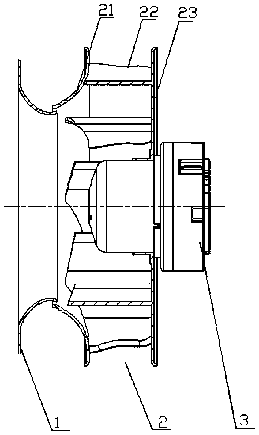
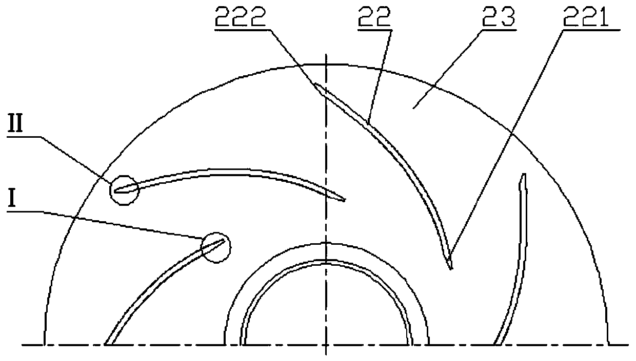
[0028] refer to figure 1 , this figure is a schematic diagram of an embodiment of a centrifugal fan of the present invention, the fan includes: an air inlet 1, an impeller 2, a motor 3, the air inlet 1 is matched with the impeller 2, and the rotation of the motor 3 drives the impeller 2 Rotate so that the airflow is sucked into the impeller from the air inlet. Wherein the impeller 2 comprises a front disc 21, blades 22 and a rear disc 23, between the front disc 21 and the rear disc 23 are provided with a plurality of arc-shaped blades, each blade has 4 edges, and the two edges of the side are respectively connected with the front disc. 21 is connected with the rear disc 23, and the airflow enters the inside of the impeller from the inner hole of the front disc 21, and flows out from the outer periphery of the impeller after passing through the passage between each blade.

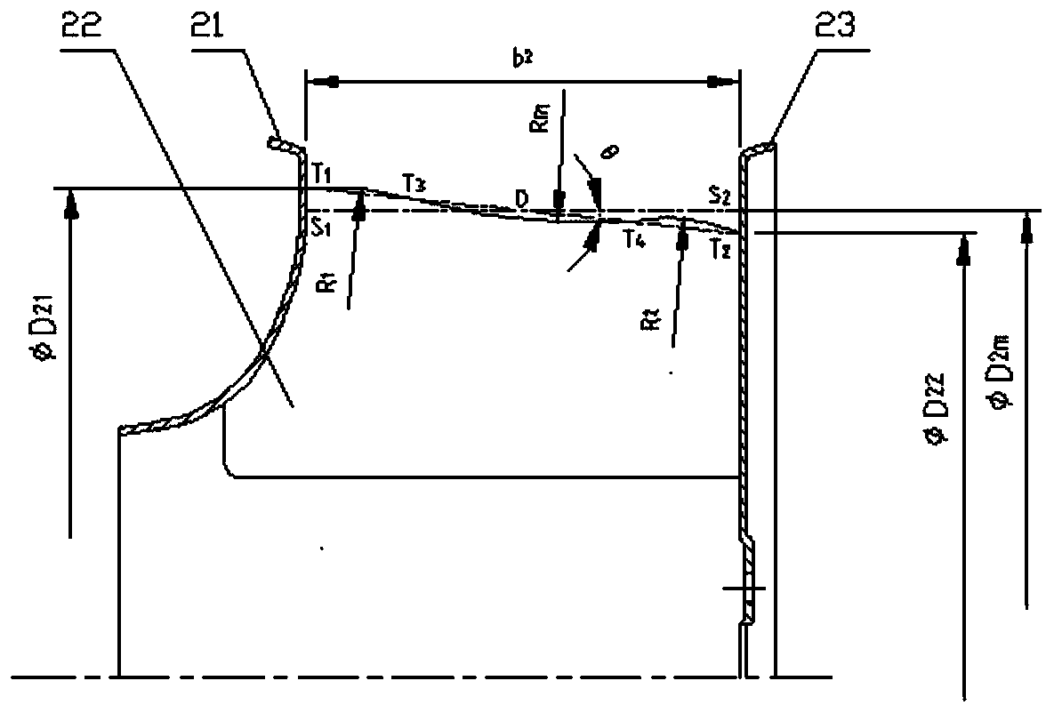
[0029] refer to figure 2 , the outer edge of the blade is a compound arc "T 1 T 3 T 4 T 2 ”, the s...

Embodiment 2

[0044] The main structural parameters of embodiment 2 of the present invention and its conventional comparison prototype 2 are as follows:

[0045] Impeller diameter (blade outer diameter): ΦD 2 = ΦD 2m =Φ570mm,

[0046] Impeller outlet width: b 2 =160mm,

[0047] Blade thickness: 2.5mm.

[0048] Compared with the conventional comparative prototype 2, the outer edge of the blade of the embodiment 2 prototype is a compound curve, and the outer edge of the blade of the comparative prototype 2 is a straight line segment parallel to the central axis, and the blade in the impeller of the embodiment 2 prototype The average value of the outer diameter is equal to the value of the outer diameter of the blade of the comparative prototype 2. The inner diameter and outer diameter of the blade of the prototype of Example 2 have been chamfered, and the blades of the comparative prototype 2 have not been chamfered. The motors and operating speeds are the same.

[0049] The data compar...


PUM


Abstract

The invention discloses an impeller for a centrifugal ventilating machine. The impeller comprises a front disc, a rear disc, and arc-shaped blades arranged between the front disc and the rear disc. The outer edge of each blade of the impeller is of an arc line shape and formed by compositing multiple sections of arc lines. Meanwhile, non-working faces of the outer edge and the inner edge of each blade are subjected to chamfering treatment, and performance and efficiency of the ventilating machine are improved.

Description

technical field [0001] The invention relates to the technical field of ventilators, in particular to an impeller of a centrifugal ventilator. Background technique [0002] When the centrifugal fan is running normally, vortices will be generated when the airflow passes through the trailing edge of the blades, and these vortices will periodically fall off from the trailing edge of the blades, which will not only affect the efficiency of the fan, but also generate noise. Usually, the projection of the edge of the outer diameter outlet of the impeller of the centrifugal fan (mostly perpendicular to the plane of the main body of the rear plate) on the meridian plane view is a straight line segment parallel to the central axis of the impeller, and the length of the line segment is the width of the impeller outlet. That is, from the front disc side to the rear disc side, the radii of the outer edges of the blades relative to the axis center are equal. During the operation of the b...

Claims


Application Information

Patent Timeline
Patent Type & Authority Applications(China)
IPC IPC(8): F04D29/28F04D29/30
CPCF04D29/282F04D29/30
Inventor 裘霖富徐天赐张职锋马杰凯俞晓骏刘伟
Owner 浙江科贸智能机电股份有限公司
Why Eureka
Try Eureka