Lubricating structure and mechanical lubricating device having same

A technology of lubricating structure and center position, applied in mechanical equipment, engine lubrication, engine components, etc., can solve the problems of thin oil film thickness, low oil film pressure, low oil film bearing capacity, etc., to reduce direct contact and improve oil storage. capacity, the effect of increasing service life and stability

Active Publication Date: 2020-12-08
ZHUHAI GREE REFRIGERATION TECH CENT OF ENERGY SAVING & ENVIRONMENTAL PROTECTION
View PDF7 Cites 0 Cited by
  • Summary
  • Abstract
  • Description
  • Claims
  • Application Information

AI Technical Summary

Problems solved by technology

[0003] However, the oil film pressure on the rotating lubricating end surface in the current prior art is relatively small, and under heavy load, high speed and pressure or various complex working conditions, the oil film bearing capacity will be small or the thickness of the oil film will become thinner. Furthermore, the contact between the end faces causes wear and leads to failure of the lubricating end face; and the oil storage capacity of the rotating lubricating end face in the prior art is poor, and the oil film ruptures or the oil film becomes thinner under high load and high speed conditions, resulting in end face wear;

Method used


Image

  • Lubricating structure and mechanical lubricating device having same
  • Lubricating structure and mechanical lubricating device having same
  • Lubricating structure and mechanical lubricating device having same

Examples


Embodiment Construction

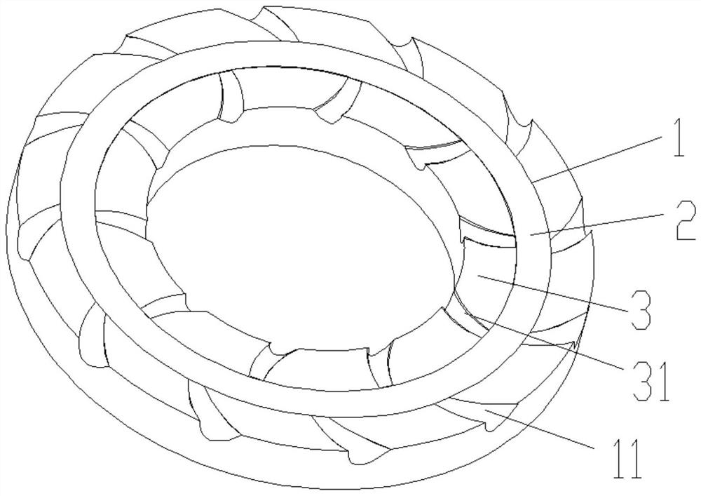
[0030] see in conjunction figure 1 As shown, according to an embodiment of the present application, a lubricating structure includes: an annular lubricating end surface, which includes an annular first converging area 1, an annular dam area 2 and an annular The second converging area 3 is formed, the first converging area 1 and the second converging area 3 are arranged circumferentially around the center point of the lubricating end face; the first converging area 1 is provided with a plurality of The first helical groove 11 extending on the outer peripheral side, a plurality of first helical grooves 11 are arranged circumferentially along the center position of the first converging area 1; and / or, the second converging area 3 is provided with a plurality of A second helical groove 31 extending from the outer peripheral side to the inner peripheral side of 3 , and a plurality of second helical grooves 31 are circumferentially arranged along the central position of the second c...


PUM


Abstract

The invention provides a lubricating structure and a sealing structure with the same. The lubricating structure comprises an annular lubricating end face. The annular lubricating end face comprises acircular first converging area, a circular dam area and a circular second converging area in sequence in the direction towards the center. The first converging area and the second converging area areeach circumferentially arranged around the central point of the lubricating end face. The first converging area is provided with a plurality of first spiral grooves extending from the inner circumferential side of the first converging area to the outer circumferential side, and the first spiral grooves are circumferentially arranged around the center of the first converging area; and / or, the second converging area is provided with a plurality of second spiral grooves extending from the outer circumferential side of the second converging area to the inner circumferential side, and the second spiral grooves are circumferentially arranged around the center of the second converging area. According to the lubricating structure, under the high load, high speed or extreme once oiling and oil lacking conditions, the high oil storage capacity can be kept, and the direct contact between the end faces of a friction pair is reduced.

Description

technical field [0001] The application belongs to the technical field of mechanical lubrication, and in particular relates to a lubricating structure and a mechanical lubricating device having the same. Background technique [0002] At present, the rotary fluid lubricated end face is widely used in various industrial occasions as a good lubricating and mechanical lubricating structure. [0003] However, the oil film pressure on the rotating lubricating end surface in the current prior art is relatively small, and under heavy load, high speed and pressure or various complex working conditions, the oil film bearing capacity will be small or the thickness of the oil film will become thinner. Furthermore, the contact between the end faces causes wear and leads to failure of the lubricating end face; and the oil storage capacity of the rotating lubricating end face in the prior art is poor, and the oil film ruptures or the oil film becomes thinner under high load and high speed c...

Claims


Application Information

Patent Timeline
Patent Type & Authority Patents(China)
IPC IPC(8): F16N9/02
CPCF16N9/02
Inventor 刘鹏飞丁少鹏史正良关蕴奇
Owner ZHUHAI GREE REFRIGERATION TECH CENT OF ENERGY SAVING & ENVIRONMENTAL PROTECTION
Why Eureka
Try Eureka