Array LED microstructure for obtaining uniform light spots

A technology of LED structure and microstructure, which is applied to semiconductor devices of light-emitting elements, light sources, electric light sources, etc., can solve the problems of uneven distribution of light intensity, uneven distribution of light intensity of a single LED, affecting the optical error of image capture, etc.

Inactive Publication Date: 2019-12-13
INTERFACE TECH CHENGDU CO LTD +2
View PDF2 Cites 0 Cited by
  • Summary
  • Abstract
  • Description
  • Claims
  • Application Information

AI Technical Summary

Problems solved by technology

But the LED light source has the following disadvantages at the same time: 1, a single LED is small in size but low in power, and the array LED can obtain high power but is too large in size; 2, a single LED only has high brightness in the middle of the receiving screen, and the brightness at the edge is fast Weaken, the light intensity is not evenly distributed; 3, the light intensity distribution of a single LED is uneven, and the array LED can get uniform light, but the volume is too large, and there is a contradiction between the uniformity of the LED light output and the volume of the LED
In the above-mentioned first disadvantage, a single LED is small in size but low in power, array LEDs can obtain high power but are too large in size, and current devices are developing in the direction of high brightness and miniaturization
The above-mentioned second shortcoming means that a single LED only has high brightness in the middle of the receiving screen, while the brightness at the edge is rapidly weakened, and the light intensity is not evenly distributed. If it is used in time-of-flight (TOF) depth sensing, it will affect Optical errors to image capture
The above-mentioned third disadvantage means that the light intensity distribution of a single LED is uneven, and the array LED can obtain uniform light but the volume is too large, and there is a contradiction between the uniformity of the LED light output and the volume of the LED
[0005] It can be seen that there are still many deficiencies in the above-mentioned commonly used items, which are not really good designers and need to be improved urgently.

Method used


Image

  • Array LED microstructure for obtaining uniform light spots
  • Array LED microstructure for obtaining uniform light spots
  • Array LED microstructure for obtaining uniform light spots

Examples


Embodiment Construction

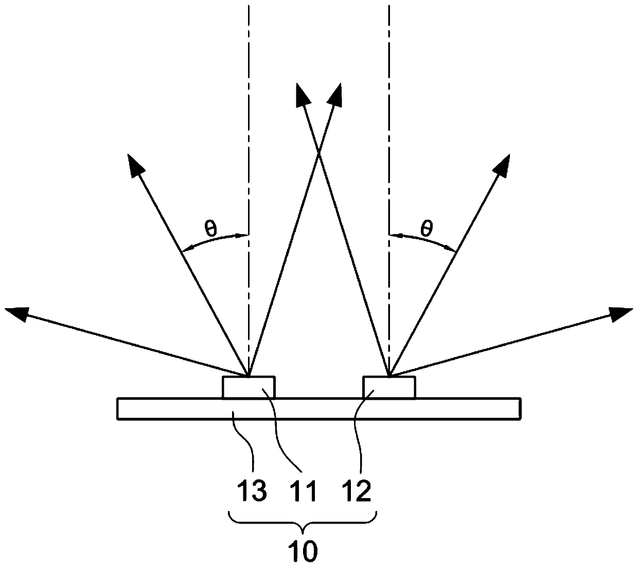
[0025] The present invention is about an "array LED microstructure for obtaining uniform light spots", please refer to figure 1 As shown, the array LED microstructure for obtaining a uniform light spot in the present invention mainly includes: an LED unit 10 .

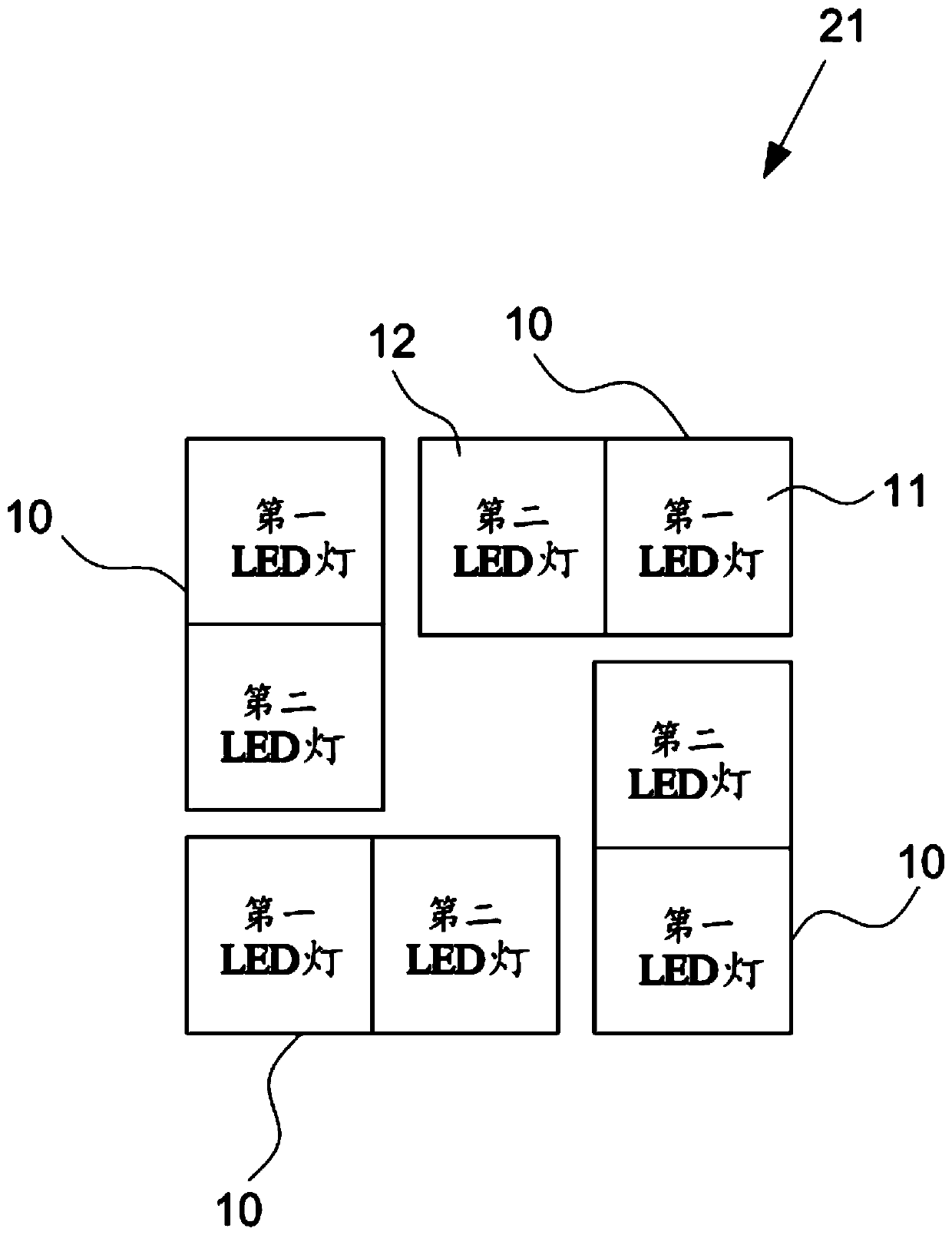
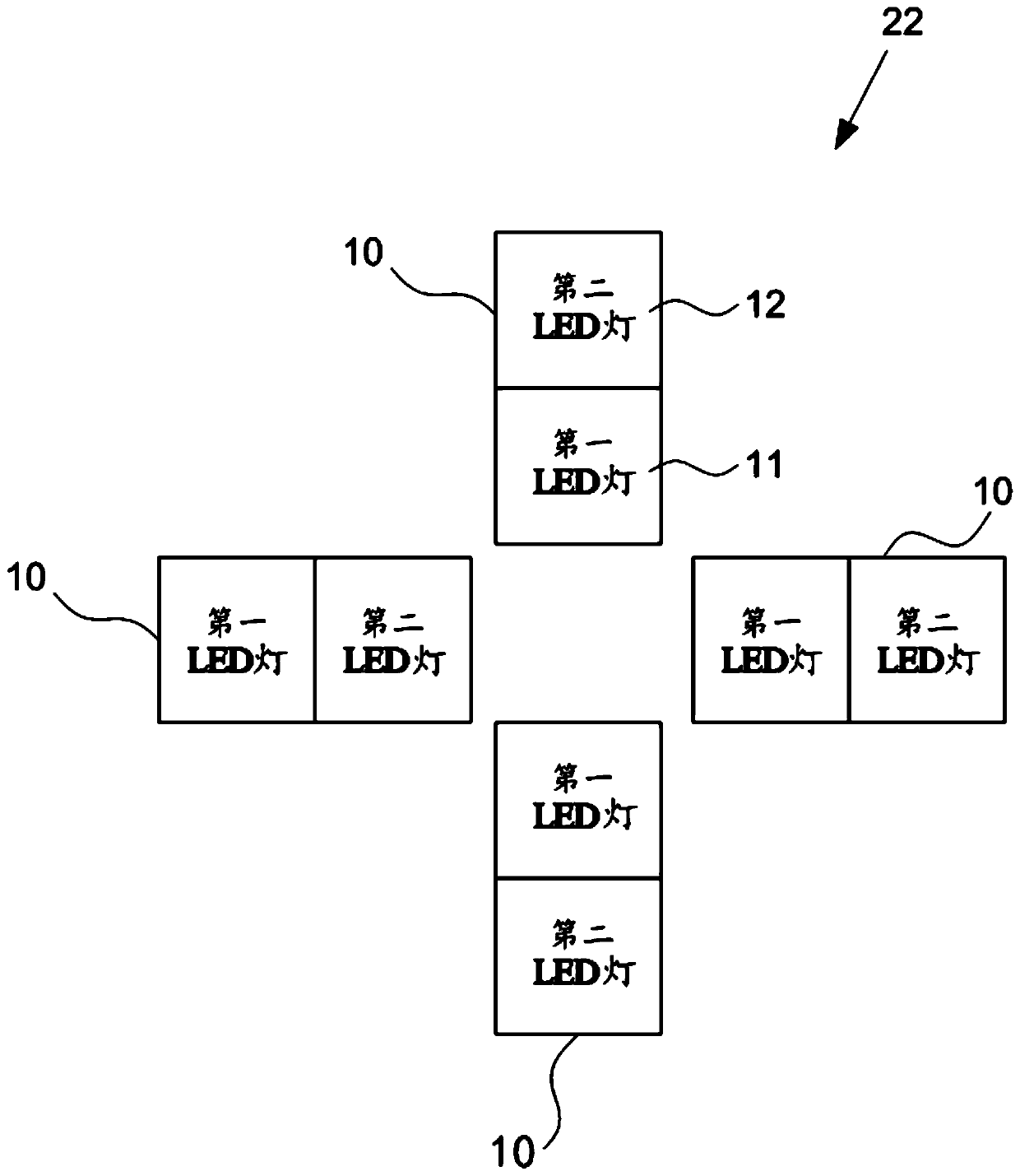
[0026] Wherein, the LED unit 10 has a first LED lamp 11 and a second LED lamp 12, the first LED lamp 11 is set on a circuit 13 at an inclination angle Θ to the center line of -16 degrees to -22.2 degrees, and The second LED lamp 12 is also arranged on the circuit 13, at a distance of 10mm (millimeters) from the first LED lamp 11, and is arranged on the circuit 13 at an inclination angle Θ to the center line of +16° to +22.2° .

[0027] With the composition of the above components, the first and second LED lamps 11, 12 are designed to have an inclination angle Θ relative to the center line, successfully solving the problem of insufficient brightness of a single LED, and the first and second LED lamps 11, 12 In the cas...


PUM


Abstract

Disclosed is an array LED microstructure for obtaining uniform light spots. The array LED microstructure comprises an LED unit, wherein the LED unit is provided with a first LED lamp and a second LEDlamp, wherein the first LED lamp is arranged on a circuit at an inclination angle of -16 degrees to -22.2 degrees with a center line; and the second LED lamp is also arranged on the circuit with a distance of 10mm from the first LED lamp, and at an inclination angle of +16 degrees to +22.2 degrees with the center line. Therefore, through the design of the first LED lamp and the second LED lamp with the inclined angles relative to the center line, the problem of insufficient brightness of the single LED is successfully solved; and in the situation that the first LED lamp and the second LED lampare close to each other, the luminous spots are uniform, so that the problem that the single LED is not uniform in luminescence is solved, and the miniaturization of the structure can be ensured.

Description

technical field [0001] The present invention is an array LED microstructure for obtaining uniform light spots, especially a structure in which the two LED lamps of the LED unit are tilted at an angle so that the light spots of the two LED lights are uniform when the two LED lights are close to each other. By. Background technique [0002] Press, whether it is the time-of-flight (TOF) depth sensing module of the mobile phone, or the module of the micro-projector or the augmented reality (AR) glasses, the most commonly used light source is the LED light source. Sexual demands are very high. For time-of-flight (TOF) depth sensing modules, the uniformity of the light source projected on the object will cause errors in the detection distance; for micro-projectors and augmented reality (AR) glasses, the uniformity of the light source will affect the projection Picture quality. Therefore, in these systems, the uniformity of the light source is an important factor affecting the p...

Claims


Application Information

Patent Timeline
Patent Type & Authority Applications(China)
IPC IPC(8): F21S8/00F21V19/00F21Y115/10
CPCF21S8/00F21V19/001F21Y2115/10
Inventor 尤贝陈忠君庄胜钧
Owner INTERFACE TECH CHENGDU CO LTD
Why Eureka
Try Eureka