
Double-system microchannel collecting pipe

A micro-channel and dual-system technology, applied to tubular components, lighting and heating equipment, heat exchange equipment, etc., can solve the problems of high difficulty and high cost, and achieve the effect of reducing the charging amount, small volume, and improving the heat transfer coefficient

Pending Publication Date: 2019-12-13
江苏科菱库精工科技有限公司
View PDF1 Cites 0 Cited by
  • Summary
  • Abstract
  • Description
  • Claims
  • Application Information

AI Technical Summary

Problems solved by technology

In product design, in order to improve part of the energy efficiency of the product, dual systems will be used, and only one system will be used when part of the load is used. Sometimes, half of the fin area of ​​the heat exchanger is not used, and some products adopt the method of cross-arranging heat-exchanging flat tubes, which is very difficult and expensive

Method used


Image

  • Double-system microchannel collecting pipe
  • Double-system microchannel collecting pipe
  • Double-system microchannel collecting pipe

Examples


Embodiment approach 1

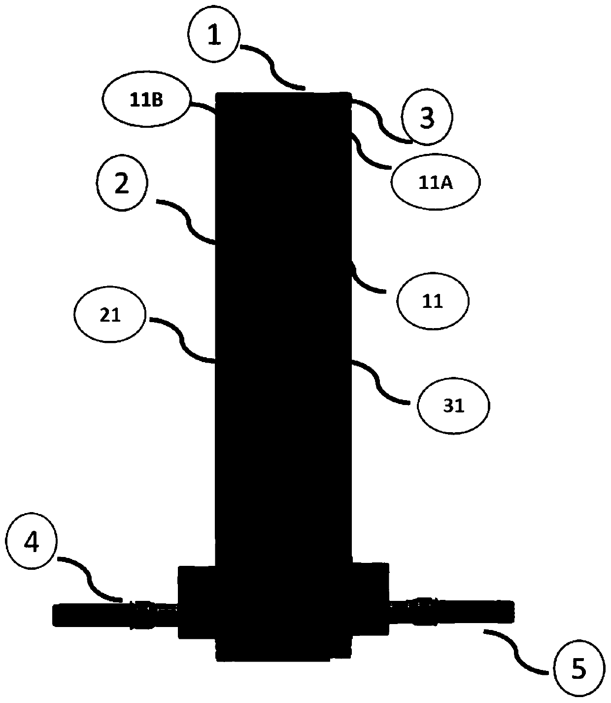
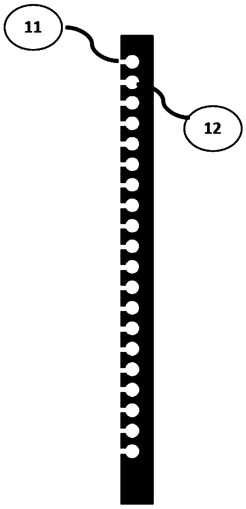
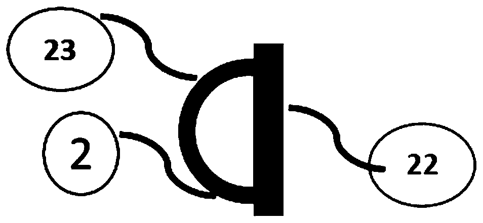
[0035] The refrigerant of the first system flows in from the first connection pipe 4 and enters the first communication part 2. The refrigerant of the first system flows in the communication channel of the first communication part 2, enters the channel 12 through the through hole 22A, and enters the corresponding first system flat. The pipe interface 11A enters the heat exchange flat tube of the first system for heat exchange; the refrigerant of the second system flows in from the second connecting pipe 5 and enters the second communication part 3, and the refrigerant of the second system flows through the communication channel of the second communication part 3 The flow enters the channel 12 through the through hole 33A, enters the corresponding second system flat tube interface 11B, and enters the second system heat exchange flat tube for heat exchange.

Embodiment approach 2

[0037] The refrigerant of the first system flows out from the flat tube, passes through the flat tube interface 11A of the first system, enters the channel 12, passes through the through hole 22A, enters the first communication part 2 together, and flows out from the first connecting pipe 4; the refrigerant of the second system flows from the The flat tube flows out, passes through the flat tube interface 11B of the second system, enters the channel 12 , passes through the through hole 33A, enters the second communication part 3 together, and flows out from the second connecting pipe 5 .


PUM


Abstract

The invention relates to the technical field of microchannel heat exchangers, in particular to a double-system microchannel collecting pipe. The double-system microchannel collecting pipe comprises acore body part, a first communication part and a second communication g part, wherein the first communication part belongs to a first system and the second communication part belongs to a second system; flat pipe connectors and a passage are uniformly distributed on the core body part; the flat pipe connectors are used for butting flat pipes and comprise a first system flat pipe connector and a second system flat pipe connector; the first system flat pipe connector and the second system flat pipe connector communicate with the passage; one part of the passage communicates with the first communication part, and the other part of the passage communicates with the second communication part; and the first communication part and the second communication part are respectively connected with a plurality of first connecting pipes and second connecting pipes. By adopting the structure and the method, and compared with an existing microchannel collecting pipe with the crossed flat tube arrangement, the double-system microchannel collecting pipe has the advantages that the internal volume is smaller, the refrigerant charge is further reduced by about 30%, and environmental friendliness and system safety are facilitated.

Description

technical field [0001] The invention relates to the technical field of microchannel heat exchangers, in particular to a dual-system microchannel header and a method for using the same. Background technique [0002] The micro-channel heat exchanger adopts flat tubes, the inner channel hydraulic diameter is small, the boundary layer is small, the heat transfer coefficient in the tube is high, the speed of the air is uniform in the direction of travel, and the heat transfer coefficient of the air on the fin side is high. It is welded and has no expansion joints. Thermal resistance; due to such characteristics, microchannel heat exchangers are often used in occasions that improve energy efficiency, reduce weight, compact structure, and reduce refrigerant charge, and are the development direction of air-side heat exchangers. Existing microchannel heat exchangers include headers, inlet and outlet tubes, and fins. The headers are round tubes. The diameter of the headers is 3 to 5 m...

Claims


Application Information

Patent Timeline
IPC IPC(8): F28F9/02F28F9/26F28F1/02F25B39/00
CPCF28F9/02F28F9/26F28F1/022F25B39/00
Inventor 赵永峰薛炎
Owner 江苏科菱库精工科技有限公司
Features
  • Generate Ideas
  • Intellectual Property
  • Life Sciences
  • Materials
  • Tech Scout
  • Unparalleled Data Quality
  • Higher Quality Content
  • 60% Fewer Hallucinations
Learn More