
Line recognition module, line recognition device and display device

A pattern and module technology, applied in the field of pattern identification, can solve the problems of limited application scenarios of fingerprint identification modules, large size of fingerprint identification modules, and limitations in application fields, and achieve improved application adaptability, low cost, and low material cost. get easy results

Pending Publication Date: 2019-12-13
BOE TECH GRP CO LTD +1
View PDF10 Cites 4 Cited by
  • Summary
  • Abstract
  • Description
  • Claims
  • Application Information

AI Technical Summary

Problems solved by technology

[0002] In recent years, the application fields and identification methods of fingerprints have become more and more extensive. At present, there are many schemes for identifying fingerprints. The size of the fingerprint identification module is limited by the size of the prism, resulting in a large size of the entire fingerprint identification module, and its application field is greatly limited. However, the use of optical fibers and other imaging structures to identify fingerprints has reduced the thickness of the fingerprint module. , but its cost becomes large
In summary, the application scenarios of fingerprint identification modules provided by the existing technology are limited

Method used


Image

  • Line recognition module, line recognition device and display device
  • Line recognition module, line recognition device and display device
  • Line recognition module, line recognition device and display device

Examples


Embodiment Construction

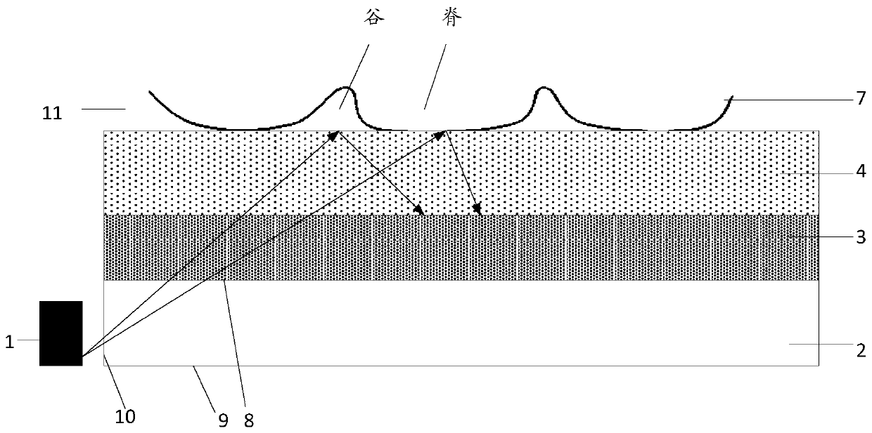
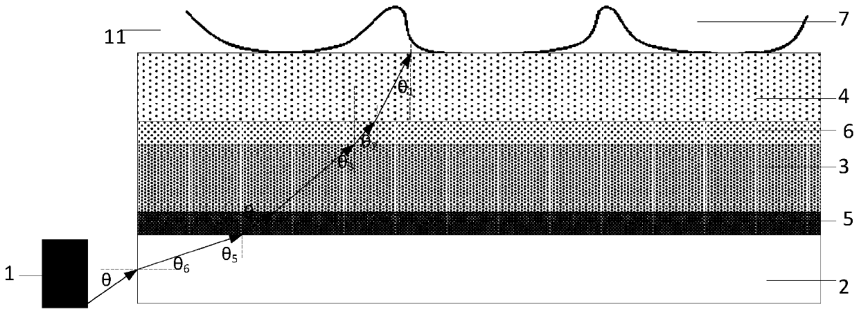
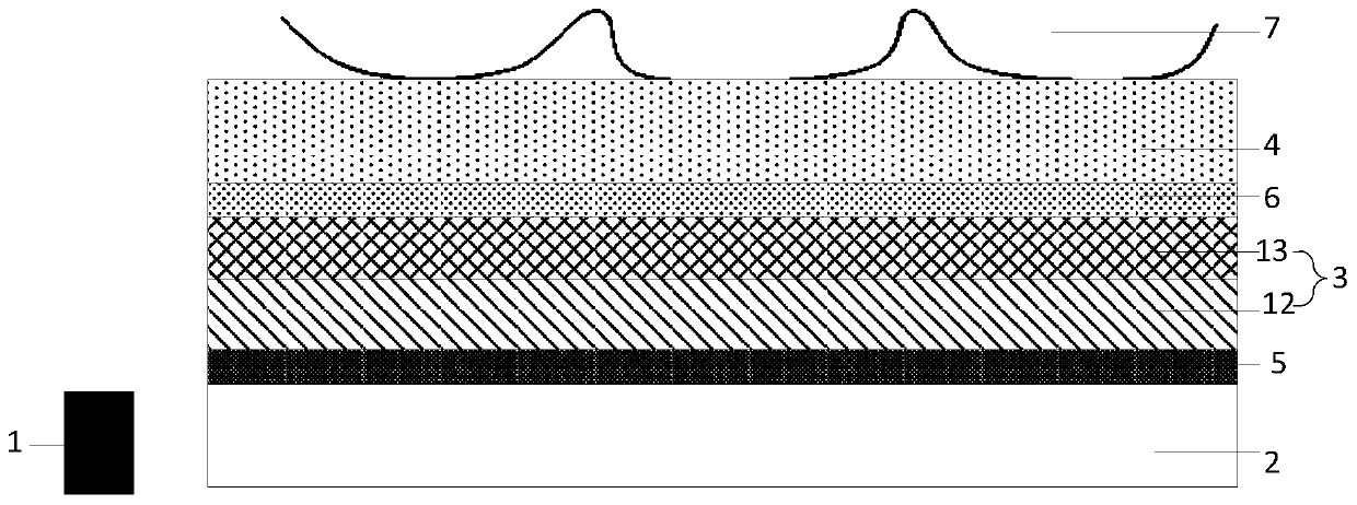
[0027] The embodiment of the present application provides a texture recognition module, such as figure 1 As shown, the pattern recognition module includes: a light source 1, a light guide layer 2 stacked in sequence, an optical sensor layer 3, and a light-transmitting cover plate 4; the light guide layer has: a first layer facing the optical sensor layer Surface 8, the second surface 9 away from the optical sensor layer, and the side 10 connecting the first surface 8 and the second surface 9; the light source 1 is located on the side 10; on the transparent cover On the side of the plate 4 away from the optical sensor layer 3 , the refractive index n0 of the medium 11 adjacent to the transparent cover plate 4 is smaller than the refractive index n1 of the transparent cover plate 4 .

[0028] In the pattern recognition module provided by the embodiment of the present application, since the refractive index of the medium adjacent to the transparent cover is smaller than that of t...


PUM


Abstract

The invention discloses a line recognition module, a line recognition device and a display device, and aims to provide a line recognition module based on a total reflection principle and increase application scenes of the line recognition module. The embodiment of the invention provides a line recognition module. The line recognition module comprises a light source, a light guide layer, an opticalsensor layer and a light-transmitting cover plate, wherein the light guide layer, the optical sensor layer and the light-transmitting cover plate are stacked in sequence. Wherein the light guide layer is provided with a first surface facing the optical sensor layer, a second surface deviating from the optical sensor layer, and a side surface connecting the first surface and the second surface; the light source is positioned on the side surface; and on one side, deviating from the optical sensor layer, of the light-transmitting cover plate, the refractive index n0 of the medium adjacent to thelight-transmitting cover plate is smaller than the refractive index n1 of the light-transmitting cover plate.

Description

technical field [0001] The present application relates to the technical field of texture recognition, in particular to a texture recognition module, a texture recognition device and a display device. Background technique [0002] In recent years, the application fields and identification methods of fingerprints have become more and more extensive. At present, there are many schemes for identifying fingerprints. The size of the fingerprint identification module is limited by the size of the prism, resulting in a large size of the entire fingerprint identification module, and its application field is greatly limited. However, the use of optical fibers and other imaging structures to identify fingerprints has reduced the thickness of the fingerprint module. , but its cost becomes very large. To sum up, the application scenarios of the fingerprint identification module provided by the prior art are limited. Contents of the invention [0003] The embodiment of the present app...

Claims


Application Information

Patent Timeline
Patent Type & Authority Applications(China)
IPC IPC(8): G06K9/00
CPCG06V40/1324G06V40/1318G06V40/1359
Inventor 陶京富程鹏飞禹璐常康乐桑建
Owner BOE TECH GRP CO LTD
Learn More