Hydraulic spring operating mechanism

A technology of operating mechanism and hydraulic spring, which is applied in the direction of contact operating mechanism, protection switch operation/release mechanism, power device inside the switch, etc., can solve the problems of energy waste, sealing failure, etc., to improve the compactness of the structure, reduce the Waste, the effect of avoiding energy waste

Active Publication Date: 2019-12-13
PINGGAO GRP +1
View PDF10 Cites 0 Cited by
  • Summary
  • Abstract
  • Description
  • Claims
  • Application Information

AI Technical Summary

Problems solved by technology

[0005] The purpose of the present invention is to provide a hydraulic spring operating mechanism, which is used to solve the problems of energy waste and potential safety hazards of sealing failure caused by the operating mechanism in the prior art.

Method used


Image

  • Hydraulic spring operating mechanism
  • Hydraulic spring operating mechanism
  • Hydraulic spring operating mechanism

Examples


Embodiment 1

[0034] The hydraulic spring operating mechanism in this embodiment is used to control the closing and opening of the high voltage circuit breaker.

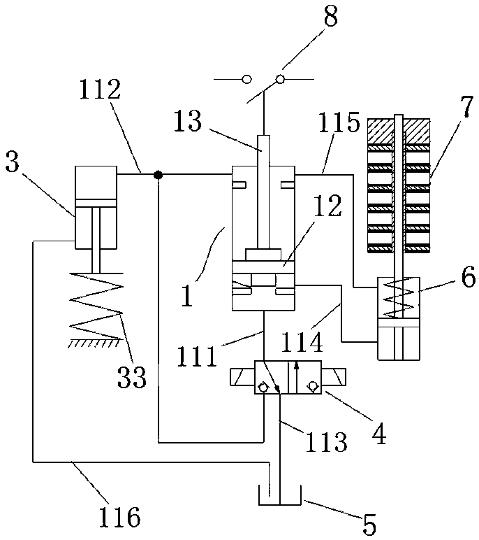
[0035] Such as figure 1 As shown, the hydraulic spring operating mechanism includes a working cylinder 1, a spring energy storage device 3, a hydraulic system, a power generation piston cylinder 6 and a power generation device 7, and the hydraulic system includes an electromagnetic reversing valve 4, a fuel tank 5 and an oil circuit connecting each device .

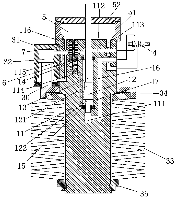
[0036] Such as figure 2 As shown, the working cylinder 1 includes a cylinder body 11 and a differential piston 12. The cylinder body 11 is provided with a working cylinder inner cavity for the differential piston 12 to move. The differential piston 12 divides the working cylinder inner cavity into an upper working high-pressure chamber 16 and the lower working differential pressure chamber 17;

[0037] Such as figure 1 with figure 2As shown, the upper side of the diffe...

Embodiment 2

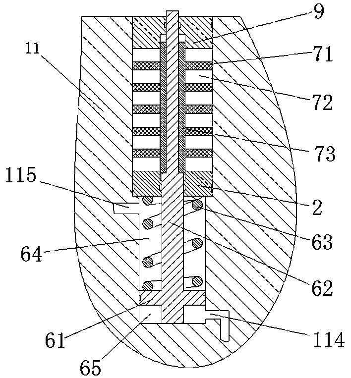
[0056] The difference with Embodiment 1 is mainly that the power generating device is different, and the power generating device in this embodiment is a linear power generating device, such as Image 6 As shown, it includes a mounting frame 102 installed between the sealing plate 2 and the sealing cover 9, and multiple sets of stator coils 101 are set on the mounting frame 102, and multiple sets of stator coils 101 are arranged along the axial direction of the generating piston rod 62, An insulating ring 104 is arranged between adjacent stator coils 101, and a sleeve-shaped permanent magnet 103 is fixedly set on the generating piston rod 62, and the sealing plate 2 is provided with a perforation for the permanent magnet 103 to pass through, and the permanent magnet 103 and the The sealing plate 2 is tightly fitted; during the upward movement of the generating piston 61 , the permanent magnet 103 cuts the magnetic induction lines generated by the stator coil 101 , thereby genera...


PUM


Abstract

The invention relates to the technical field of contact operating mechanisms of electric switches, in particular to a hydraulic spring operating mechanism. The operating mechanism comprises a workingcylinder, a spring energy storage device, a hydraulic system and a power generation piston cylinder. The operating mechanism has a buffer stroke in the closing and opening processes. The power generation piston cylinder comprises a power generation piston cylinder body and a power generation piston movably assembled in the power generation piston cylinder body, and the power generation piston is connected with a power generation device. In two cavities, separated by the power generation piston, of the power generation piston cylinder body, one cavity communicates with a high-pressure cavity ofthe energy storage oil cylinder, and the other cavity communicates with an inner cavity of the working cylinder at the upper end of the working cylinder; or, in the two cavities, separated by the power generation piston, of the power generation piston cylinder body, one cavity communicates with the high-pressure cavity of the energy storage oil cylinder, and the other cavity communicates with theinner cavity of the working cylinder at the lower end of the working cylinder. The operating mechanism is used for solving the problems that in the prior art, when an operating mechanism is used, energy is wasted, and potential safety hazards of sealing failure exist.

Description

technical field [0001] The invention relates to the technical field of a contact operating mechanism of an electric switch, in particular to a hydraulic spring operating mechanism. Background technique [0002] In the high-voltage circuit breaker, the closing and opening of the circuit breaker is generally realized by the operating mechanism, and it is maintained in the closing state or the opening state. [0003] The invention patent with authorized notification number CN106783420B records a spring energy storage type hydraulic operating mechanism for a circuit breaker, which is a commonly used operating mechanism in high-voltage circuit breakers; usually in order to improve For the mechanical life of the circuit breaker, a buffer stroke will be set during the closing process of the differential piston in the working cylinder of the operating mechanism, and a buffer stroke will also be set during the opening process of the differential piston. The buffer stroke is generally...

Claims


Application Information

Patent Timeline
Patent Type & Authority Applications(China)
IPC IPC(8): H01H3/60H01H71/10H01H3/24
CPCH01H3/24H01H3/605H01H71/10
Inventor 雷琴李宁韩国辉刘宇李海文刘煜程军强张南林张进科程晓培胡超然杨秋蓉
Owner PINGGAO GRP
Why Eureka
Try Eureka