Mixer truck power system control method

A power system and control method technology, applied in cement mixing devices, chemical instruments and methods, vehicle components, etc., can solve problems such as high pollution and high fuel consumption, and achieve the effect of reducing fuel consumption and emissions

Inactive Publication Date: 2021-04-02
河北中瑞汽车制造有限公司
View PDF5 Cites 1 Cited by
  • Summary
  • Abstract
  • Description
  • Claims
  • Application Information

AI Technical Summary

Problems solved by technology

The consequences of high fuel consumption and high pollution

Method used


Image

  • Mixer truck power system control method
  • Mixer truck power system control method
  • Mixer truck power system control method

Examples


Embodiment Construction

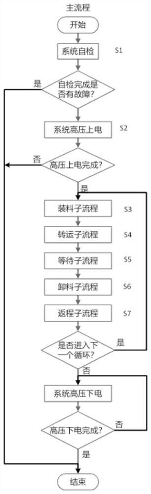
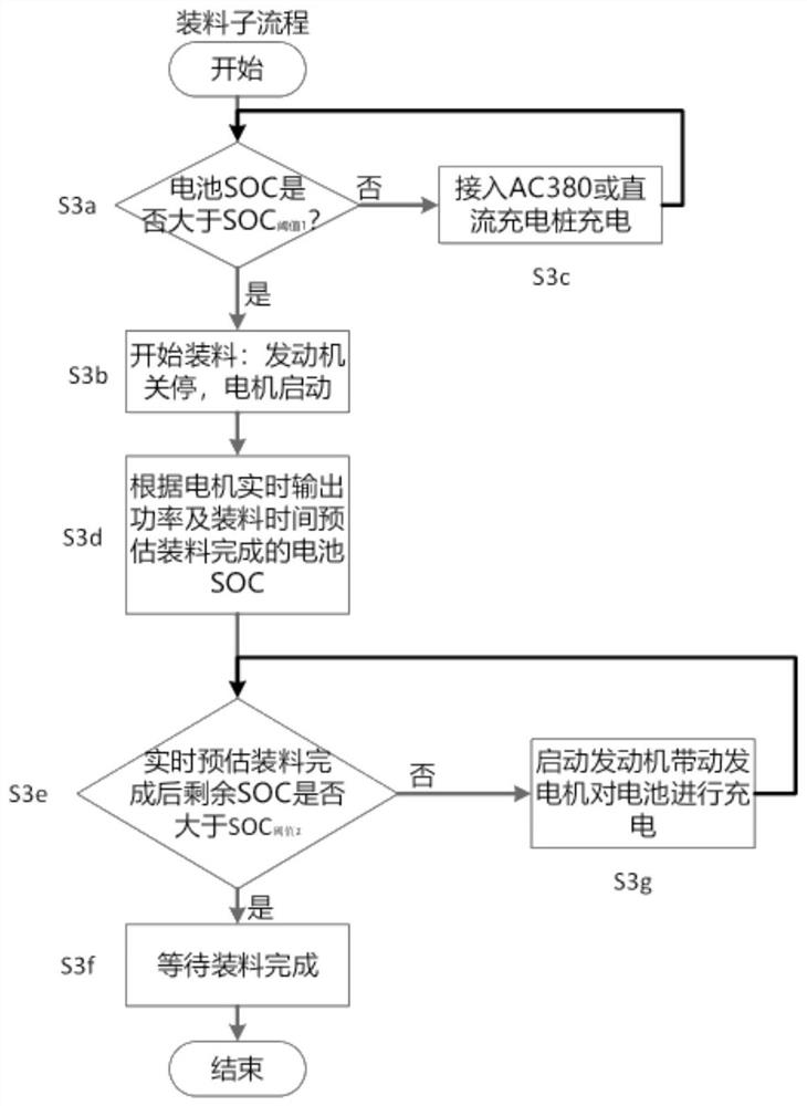
[0034] The following will clearly and completely describe the technical solutions in the embodiments of the present invention with reference to the accompanying drawings in the embodiments of the present invention. Obviously, the described embodiments are only some, not all, embodiments of the present invention. Based on the embodiments of the present invention, all other embodiments obtained by persons of ordinary skill in the art without making creative efforts belong to the protection scope of the present invention.

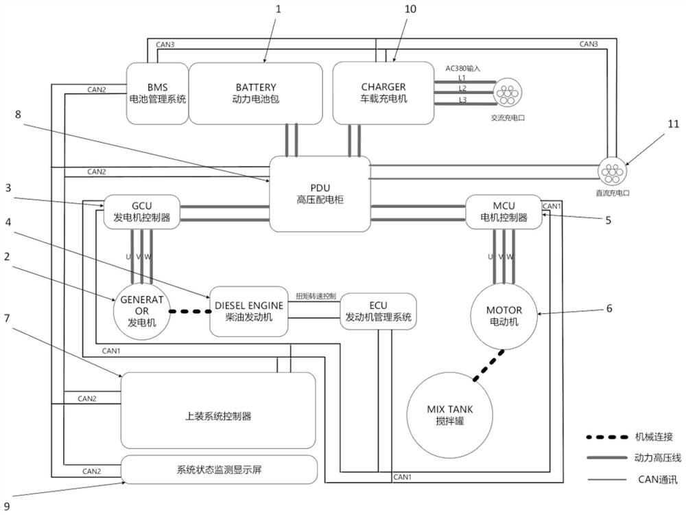
[0035] Such as figure 1 As shown, the present invention provides a power system for a mixer truck, including a motor 6 , a battery system 1 , a generator 2 and an engine 4 . Wherein, the electric motor 6 is used to drive the stirring tank of the mixer truck to rotate, that is, the electric motor 6 drives the stirring tank to rotate through the reduction box. The battery system 1 is electrically connected with the motor 6 and the generator 2 , and is used for ...


PUM


Abstract

The invention discloses a mixer truck power system control method which comprises loading, transferring, waiting, unloading and returning processes, and the waiting process comprises the steps of judging whether waiting is completed or not, if yes, stopping a generator and stopping an engine, if not, and judging whether waiting time exceeds M minutes or not, if yes, starting the engine to make thegenerator work, if not, making a motor to run continuously. According to the invention, a battery supplies power to the motor, and the motor drives a stirring tank to rotate without depending on theoutput power of the engine of the mixer truck, so that the stirring tank can still be driven to normally perform stirring operation when the engine is in a low-rotating-speed, idling or shutdown state, and the oil consumption and the emission are further greatly reduced.

Description

[0001] This application is a divisional application for an invention patent with the application number 202010442950.5 and the name is the power system and its control method for the mixer truck. The application date of the original application is May 22, 2020 technical field [0002] The invention relates to the technical field of engineering vehicles, in particular to a control method for a power system mounted on a mixer truck. Background technique [0003] In the prior art, the mixer truck generally uses a diesel engine as a power source to drive the vehicle, and at the same time drives the hydraulic system through the power take-off to drive the mixer tank of the bodywork system to rotate. In any state as long as the mixing tank is working, the diesel engine must keep working. Caused the consequence of high fuel consumption and high pollution. Especially when working in a closed environment (such as a tunnel, etc.), air pollution and noise pollution need to be strictly...

Claims


Application Information

Patent Timeline
Patent Type & Authority Applications(China)
IPC IPC(8): B60P3/16B60R16/03B60R16/033B28C5/42
CPCB60P3/16B60R16/033B28C5/421B28C5/422B28C5/4203B60R16/0307
Inventor 杨长青夏立民杨娟李志波
Owner 河北中瑞汽车制造有限公司
Why Eureka
Try Eureka