PFC circuit, current compensation method of input capacitor and power conversion circuit

A power conversion circuit and input capacitor technology, applied in the direction of high-efficiency power electronic conversion, output power conversion device, electrical components, etc. Small influence, the effect of increasing the PF value

Active Publication Date: 2019-12-13
英麦科(厦门)微电子科技有限公司
View PDF7 Cites 2 Cited by
  • Summary
  • Abstract
  • Description
  • Claims
  • Application Information

AI Technical Summary

Problems solved by technology

[0007] While the existing compensation current i cbb There are two main methods: a. reduce the capacitance value of the input capacitor cbb, but it will affect the normal operation of low voltage and EMI; b. slope compensation, such as image 3 as shown, but add i cbs It is a positive bias value, which will affect the control variable Vcomp of the power factor control circuit, and the current power changes, which is not easy to control

Method used


Image

  • PFC circuit, current compensation method of input capacitor and power conversion circuit
  • PFC circuit, current compensation method of input capacitor and power conversion circuit
  • PFC circuit, current compensation method of input capacitor and power conversion circuit

Examples


Embodiment Construction

[0029] To further illustrate the various embodiments, the present invention is provided with accompanying drawings. These drawings are a part of the disclosure of the present invention, which are mainly used to illustrate the embodiments, and can be combined with related descriptions in the specification to explain the operating principles of the embodiments. With reference to these contents, those skilled in the art should understand other possible implementations and advantages of the present invention. Components in the figures are not drawn to scale, and similar component symbols are generally used to denote similar components.

[0030] The present invention will be further described in conjunction with the accompanying drawings and specific embodiments.

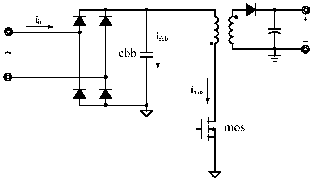
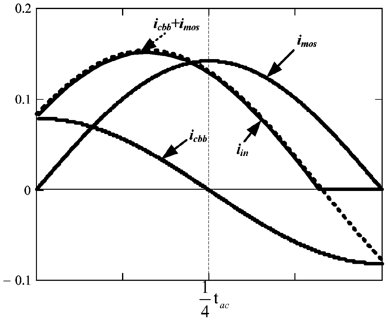
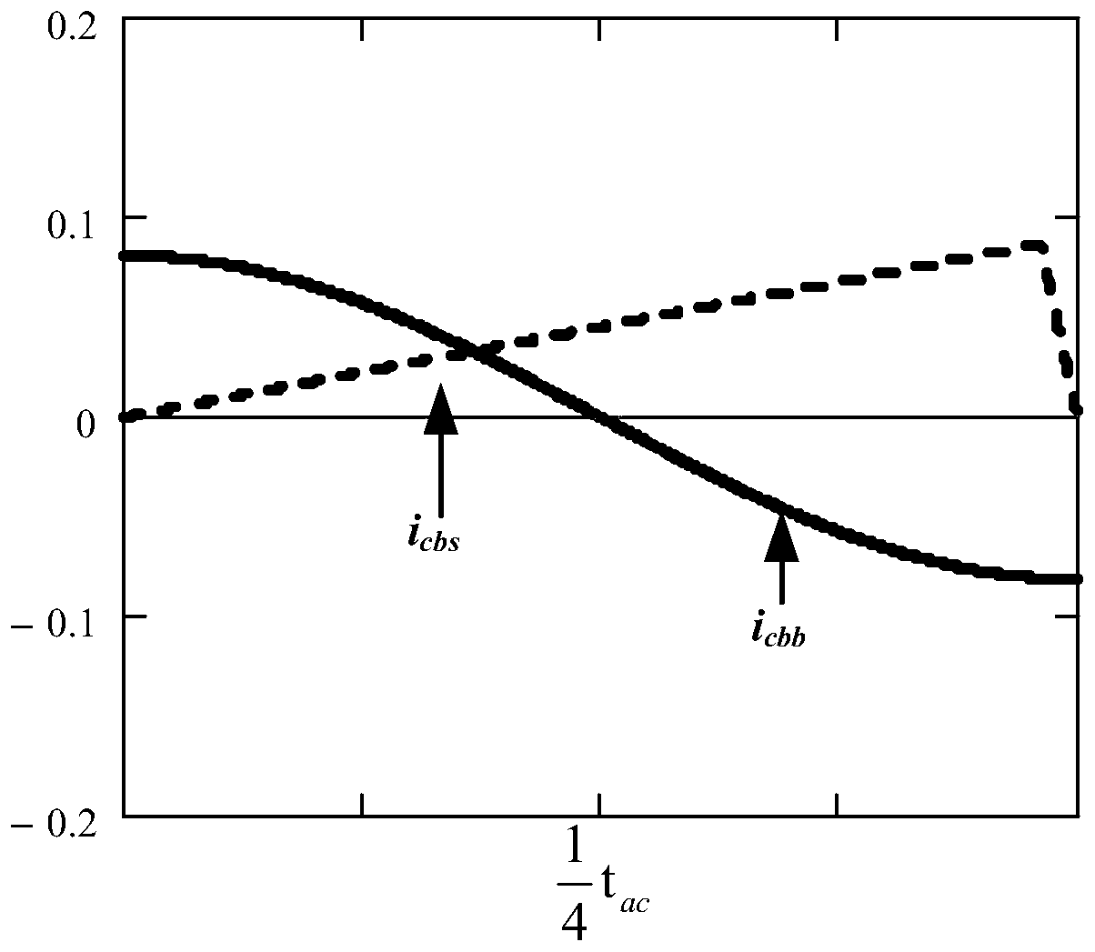
[0031] A current compensation method for an input capacitance of a PFC circuit, comprising using a compensation current i cbs The current i flowing through the input capacitance cbb of the AC input terminal of the powe...


PUM


Abstract

The invention relates to the PFC circuit technology field and especially relates to a current compensation method of an input capacitor of a PFC circuit, the PFC circuit and a power conversion circuit. The invention discloses the current compensation method of the input capacitor of the PFC circuit, the PFC circuit and the power conversion circuit. The current compensation method of the input capacitor of the PFC circuit comprises the steps that a compensation current icbs is adopted to compensate a current icbb of an input capacitor cbb flowing through an alternating current input end of thepower conversion circuit, wherein the compensation current icbs is sinusoidal current, and a frequency is twice of the frequency of an input alternating current power supply. An influence of a currentphase shift of the input capacitor of the power conversion circuit on the input current can be effectively reduced, a PF value is improved, and a current working state of the circuit is not influenced.

Description

technical field [0001] The invention belongs to the technical field of PFC circuits, and in particular relates to a PFC circuit and a current compensation method for its input capacitance and a power conversion circuit. Background technique [0002] Due to the increasing shortage of energy, people pay more and more attention to the power consumption efficiency of electronic devices. Therefore, most of the existing power conversion circuits will be equipped with a power factor correction (PFC) circuit to correct the input current to improve the efficiency of the power converter. power factor (power factor, PF), thereby improving power efficiency, such as figure 1 Shown is an existing flyback power conversion circuit with PFC circuit (the power factor control circuit is omitted). [0003] The existing PFC circuit is mainly for the current i flowing through the power switch mos mos Sinusoidal control is performed to increase the PF value. Now there are many PFC circuits and ...

Claims


Application Information

Patent Timeline
Patent Type & Authority Applications(China)
IPC IPC(8): H02M1/42
CPCH02M1/4208Y02B70/10
Inventor 郑清良
Owner 英麦科(厦门)微电子科技有限公司
Why Eureka
Try Eureka